Setup Configuration
A.1 Setup Configuration
The configuration shown in Figure 26 shows how to set up a test environment to execute O-RAN scenarios where O-DU and 0-RU are simulated using the sample application. This setup allows development and prototyping as well as testing of O-RAN specific functionality. The O-DU side can be instantiated with a full 5G NR L1 reference as well. The configuration differences of the 5G NR l1app configuration are provided below. Steps for running the sample application on the O-DU side and 0-RU side are the same, except configuration file options may be different.
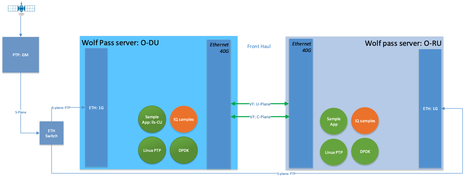
Figure 27. Setup for O-RAN Testing
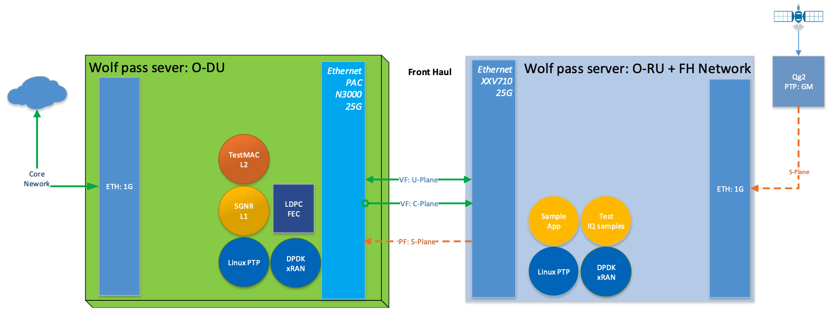
Figure 28. Setup for O-RAN Testing with PHY and Configuration C3
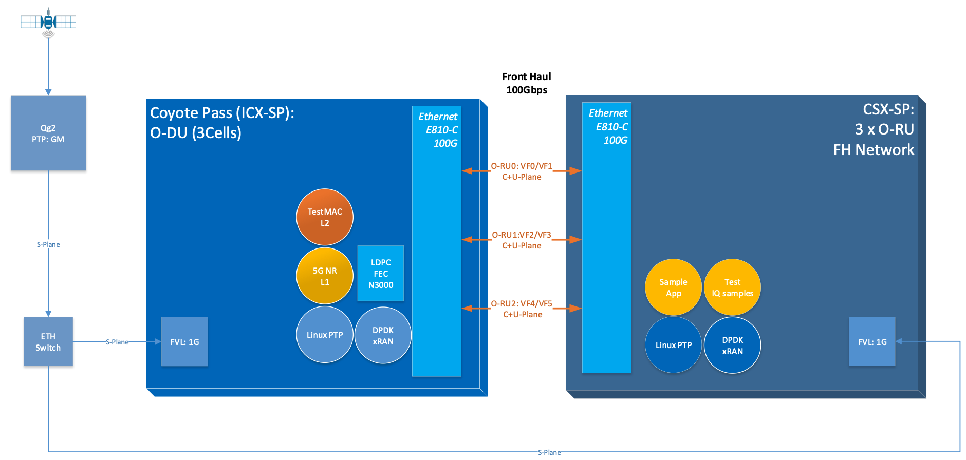
Figure 29. Setup for O-RAN Testing with PHY and Configuration C3 for Massive MIMO
A.2 Prerequisites
Each server in Figure 27 requires the following:
Wolfpass server according to recommended BOM for FlexRAN such as Intel® Xeon® Skylake Gold 6148 FC-LGA3647 2.4 GHz 27.5 MB 150W 20 cores (two sockets) or higher
Wilson City or Coyote Pass server with Intel® Xeon® Icelake CPU for Massive-MIMO with L1 pipeline testing
BIOS settings:
Intel® Virtualization Technology Enabled
Intel® VT for Directed I/O - Enabled
ACS Control - Enabled
Coherency Support - Disabled
Front Haul networking cards:
Intel® Ethernet Converged Network Adapter XL710-QDA2
Intel® Ethernet Converged Network Adapter XXV710-DA2
Intel® Ethernet Converged Network Adapter E810-CQDA2
Intel® FPGA Programmable Acceleration Card (Intel® FPGA PAC) N3000
Back (Mid) Haul networking card can be either:
Intel® Ethernet Connection X722 for 10GBASE-T
Intel® 82599ES 10-Gigabit SFI/SFP+ Network Connection
Other networking cards capable of HW timestamping for PTP synchronization.
Both Back (mid) Haul and Front Haul NIC require support for PTP HW timestamping.
The recommended configuration for NICs is:
ethtool -i enp33s0f0
driver: i40e
version: 2.14.13
firmware-version: 8.20 0x80009bd4 1.2879.0
expansion-rom-version:
bus-info: 0000:21:00.0
supports-statistics: yes
supports-test: yes
supports-eeprom-access: yes
supports-register-dump: yes
supports-priv-flags: yes
ethtool -T enp33s0f0
Time stamping parameters for enp33s0f0:
Capabilities:
    hardware-transmit (SOF_TIMESTAMPING_TX_HARDWARE)
    software-transmit (SOF_TIMESTAMPING_TX_SOFTWARE)
    hardware-receive (SOF_TIMESTAMPING_RX_HARDWARE)
    software-receive (SOF_TIMESTAMPING_RX_SOFTWARE)
    software-system-clock (SOF_TIMESTAMPING_SOFTWARE)
    hardware-raw-clock (SOF_TIMESTAMPING_RAW_HARDWARE)
PTP Hardware Clock: 4
Hardware Transmit Timestamp Modes:
    off (HWTSTAMP_TX_OFF)
    on (HWTSTAMP_TX_ON)
Hardware Receive Filter Modes:
    none (HWTSTAMP_FILTER_NONE)
    ptpv1-l4-sync (HWTSTAMP_FILTER_PTP_V1_L4_SYNC)
    ptpv1-l4-delay-req (HWTSTAMP_FILTER_PTP_V1_L4_DELAY_REQ)
    ptpv2-l4-event (HWTSTAMP_FILTER_PTP_V2_L4_EVENT)
    ptpv2-l4-sync (HWTSTAMP_FILTER_PTP_V2_L4_SYNC)
    ptpv2-l4-delay-req (HWTSTAMP_FILTER_PTP_V2_L4_DELAY_REQ)
    ptpv2-l2-event (HWTSTAMP_FILTER_PTP_V2_L2_EVENT)
    ptpv2-l2-sync (HWTSTAMP_FILTER_PTP_V2_L2_SYNC)
    ptpv2-l2-delay-req (HWTSTAMP_FILTER_PTP_V2_L2_DELAY_REQ)
    ptpv2-event (HWTSTAMP_FILTER_PTP_V2_EVENT)
    ptpv2-sync (HWTSTAMP_FILTER_PTP_V2_SYNC)
    ptpv2-delay-req (HWTSTAMP_FILTER_PTP_V2_DELAY_REQ)
The recommended configuration for Columbiaville NICs (base on Intel® Ethernet 800 Series (Columbiaville) CVL 2.3 release is:
ethtool -i enp81s0f0
driver: ice
version: 1.3.2
firmware-version: 2.3 0x80005D18
expansion-rom-version:
bus-info: 0000:51:00.0
supports-statistics: yes
supports-test: yes
supports-eeprom-access: yes
supports-register-dump: yes
supports-priv-flags: yes
ethtool -T enp81s0f0
Time stamping parameters for enp81s0f0:
Capabilities:
    hardware-transmit (SOF_TIMESTAMPING_TX_HARDWARE)
    software-transmit (SOF_TIMESTAMPING_TX_SOFTWARE)
    hardware-receive (SOF_TIMESTAMPING_RX_HARDWARE)
    software-receive (SOF_TIMESTAMPING_RX_SOFTWARE)
    software-system-clock (SOF_TIMESTAMPING_SOFTWARE)
    hardware-raw-clock (SOF_TIMESTAMPING_RAW_HARDWARE)
PTP Hardware Clock: 1
Hardware Transmit Timestamp Modes:
    off (HWTSTAMP_TX_OFF)
    on (HWTSTAMP_TX_ON)
Hardware Receive Filter Modes:
    none (HWTSTAMP_FILTER_NONE)
    all (HWTSTAMP_FILTER_ALL)

Recommended version of
iavf driver 4.0.2
ICE COMMS Package version 1.3.24.0
Note. If your firmware version does not match with the ones in the output images, you can download the correct version from the Intel Download Center. It is Intel’s repository for the latest software and drivers for Intel products. The NVM Update Packages for Windows*, Linux*, ESX*, FreeBSD*, and EFI/EFI2 are located at:
https://downloadcenter.intel.com/download/24769 (700 series)
https://downloadcenter.intel.com/download/29736 (E810 series)
PTP Grand Master is required to be available in the network to provide synchronization of both O-DU and RU to GPS time.
The software package includes Linux* CentOS* operating system and RT patch according to FlexRAN Reference Solution Cloud-Native Setup document (refer to Table 2). Only real-time HOST is required.
Install Intel® C++ Compiler v19.0.3 or OneAPI compiler (preferred)
Download DPDK v20.11.3
Patch DPDK with FlexRAN BBDev patch as per given release.
4. Double check that FlexRAN DPDK patch includes changes below relevant to O-RAN Front haul:
For Fortville:
diff --git a/drivers/net/i40e/i40e_ethdev.c b/drivers/net/i40e/i40e_ethdev.c
index 85a6a86..236fbe0 100644
--- a/drivers/net/i40e/i40e_ethdev.c
+++ b/drivers/net/i40e/i40e_ethdev.c
@@ -2207,7 +2207,7 @@ void i40e_flex_payload_reg_set_default(struct i40e_hw *hw)
    /* Map queues with MSIX interrupt */
    main_vsi->nb_used_qps = dev->data->nb_rx_queues -
        pf->nb_cfg_vmdq_vsi * RTE_LIBRTE_I40E_QUEUE_NUM_PER_VM;
-       i40e_vsi_queues_bind_intr(main_vsi, I40E_ITR_INDEX_DEFAULT);
+       i40e_vsi_queues_bind_intr(main_vsi, I40E_ITR_INDEX_NONE);
    i40e_vsi_enable_queues_intr(main_vsi);

    /* Map VMDQ VSI queues with MSIX interrupt */
@@ -2218,6 +2218,10 @@ void i40e_flex_payload_reg_set_default(struct i40e_hw *hw)
        i40e_vsi_enable_queues_intr(pf->vmdq[i].vsi);
    }
+       i40e_aq_debug_write_global_register(hw,
+                                       0x0012A504,
+                                       0, NULL);
+
    /* enable FDIR MSIX interrupt */
    if (pf->fdir.fdir_vsi) {
        i40e_vsi_queues_bind_intr(pf->fdir.fdir_vsi,
diff --git a/drivers/net/i40e/i40e_ethdev_vf.c b/drivers/net/i40e/i40e_ethdev_vf.c
index 001c301..6f9ffdb 100644
--- a/drivers/net/i40e/i40e_ethdev_vf.c
+++ b/drivers/net/i40e/i40e_ethdev_vf.c
@@ -640,7 +640,7 @@ struct rte_i40evf_xstats_name_off {

    map_info = (struct virtchnl_irq_map_info *)cmd_buffer;
    map_info->num_vectors = 1;
-       map_info->vecmap[0].rxitr_idx = I40E_ITR_INDEX_DEFAULT;
+       map_info->vecmap[0].rxitr_idx = I40E_ITR_INDEX_NONE;
    map_info->vecmap[0].vsi_id = vf->vsi_res->vsi_id;
    /* Alway use default dynamic MSIX interrupt */
    map_info->vecmap[0].vector_id = vector_id;
diff --git a/drivers/net/ixgbe/ixgbe_ethdev.c b/drivers/net/ixgbe/ixgbe_ethdev.c
index 26b1927..018eb8f 100644
--- a/drivers/net/ixgbe/ixgbe_ethdev.c
+++ b/drivers/net/ixgbe/ixgbe_ethdev.c
@@ -3705,7 +3705,7 @@ static int ixgbevf_dev_xstats_get_names(__rte_unused struct rte_eth_dev *dev,
        * except for 82598EB, which remains constant.
        */
        if (dev_conf->txmode.mq_mode == ETH_MQ_TX_NONE &&
-                               hw->mac.type != ixgbe_mac_82598EB)
+                               hw->mac.type != ixgbe_mac_82598EB && hw->mac.type != ixgbe_mac_82599EB)
            dev_info->max_tx_queues = IXGBE_NONE_MODE_TX_NB_QUEUES;
    }
    dev_info->min_rx_bufsize = 1024; /* cf BSIZEPACKET in SRRCTL register */
diff --git a/lib/librte_eal/common/include/rte_dev.h b/lib/librte_eal/common/include/rte_dev.h
old mode 100644
new mode 100755

for Columbiaville
diff --git a/drivers/net/ice/ice_ethdev.c b/drivers/net/ice/ice_ethdev.c
index de189daba..d9aff341c 100644
--- a/drivers/net/ice/ice_ethdev.c
+++ b/drivers/net/ice/ice_ethdev.c
@@ -2604,8 +2604,13 @@ __vsi_queues_bind_intr(struct ice_vsi *vsi, uint16_t msix_vect,

                PMD_DRV_LOG(INFO, "queue %d is binding to vect %d",
                            base_queue + i, msix_vect);
-               /* set ITR0 value */
-               ICE_WRITE_REG(hw, GLINT_ITR(0, msix_vect), 0x10);
+               /* set ITR0 value
+                * Empirical configuration for optimal real time latency
+                * reduced interrupt throttling to 2 ms
+                * Columbiaville pre-PRQ : local patch subject to change
+                */
+               ICE_WRITE_REG(hw, GLINT_ITR(0, msix_vect), 0x1);
+               ICE_WRITE_REG(hw, QRX_ITR(base_queue + i), QRX_ITR_NO_EXPR_M);
                ICE_WRITE_REG(hw, QINT_RQCTL(base_queue + i), val);
                ICE_WRITE_REG(hw, QINT_TQCTL(base_queue + i), val_tx);
        }
5.Build and install the DPDK:
See https://doc.dpdk.org/guides/prog_guide/build-sdk-meson.html
6.Make below file changes in dpdk that assure i40e to get best latency of packet processing:
--- i40e.h      2018-11-30 11:27:00.000000000 +0000
+++ i40e_patched.h      2019-03-06 15:49:06.877522427 +0000
@@ -451,7 +451,7 @@

#define I40E_QINT_RQCTL_VAL(qp, vector, nextq_type) \
    (I40E_QINT_RQCTL_CAUSE_ENA_MASK | \
-       (I40E_RX_ITR << I40E_QINT_RQCTL_ITR_INDX_SHIFT) | \
+       (I40E_ITR_NONE << I40E_QINT_RQCTL_ITR_INDX_SHIFT) | \
    ((vector) << I40E_QINT_RQCTL_MSIX_INDX_SHIFT) | \
    ((qp) << I40E_QINT_RQCTL_NEXTQ_INDX_SHIFT) | \
    (I40E_QUEUE_TYPE_##nextq_type << I40E_QINT_RQCTL_NEXTQ_TYPE_SHIFT))

--- i40e_main.c 2018-11-30 11:27:00.000000000 +0000
+++ i40e_main_patched.c 2019-03-06 15:46:13.521518062 +0000
@@ -15296,6 +15296,9 @@
        pf->hw_features |= I40E_HW_HAVE_CRT_RETIMER;
    /* print a string summarizing features */
    i40e_print_features(pf);
+
+       /* write to this register to clear rx descriptor */
+       i40e_aq_debug_write_register(hw, 0x0012A504, 0, NULL);

    return 0;
A.3 Configuration of System
1.Boot Linux with the following arguments:
cat /proc/cmdline
BOOT_IMAGE=/vmlinuz-3.10.0-1062.12.1.rt56.1042.el7.x86_64 root=/dev/mapper/centos-root ro
crashkernel=auto rd.lvm.lv=centos/root rd.lvm.lv=centos/swap intel_iommu=on iommu=pt
usbcore.autosuspend=-1 selinux=0 enforcing=0 nmi_watchdog=0 softlockup_panic=0 audit=0
intel_pstate=disable cgroup_memory=1 cgroup_enable=memory mce=off idle=poll
hugepagesz=1G hugepages=16 hugepagesz=2M hugepages=0 default_hugepagesz=1G
isolcpus=1-19,21-39 rcu_nocbs=1-19,21-39 kthread_cpus=0,20 irqaffinity=0,20
nohz_full=1-19,21-39
Boot Linux with the following arguments for Icelake CPU:
cat /proc/cmdline
BOOT_IMAGE=/vmlinuz-3.10.0-957.10.1.rt56.921.el7.x86_64
root=/dev/mapper/centos-root ro crashkernel=auto rd.lvm.lv=centos/root
rd.lvm.lv=centos/swap rhgb quiet intel_iommu=off usbcore.autosuspend=-1
selinux=0 enforcing=0 nmi_watchdog=0 softlockup_panic=0 audit=0
intel_pstate=disable cgroup_disable=memory mce=off hugepagesz=1G
hugepages=40 hugepagesz=2M hugepages=0 default_hugepagesz=1G
isolcpus=1-23,25-47 rcu_nocbs=1-23,25-47 kthread_cpus=0 irqaffinity=0
nohz_full=1-23,25-47
3. Download from Intel Website and install updated version of i40e driver if needed. The current recommended version of i40e is 2.14.13. However, any latest version of i40e after 2.9.21 expected to be functional for O-RAN FH.
4. For Columbiaville download Intel® Ethernet 800 Series (Columbiaville) CVL2.3 B0/C0 Sampling Sample Validation Kit (SVK) from Intel Customer Content Library. The current recommended version of ICE driver is 1.3.2 with ICE COMMS Package version 1.3.24.0. IAVF recommended version 4.0.2
Identify PCIe Bus address of the Front Haul NIC (Fortville):
lspci|grep Eth
86:00.0 Ethernet controller: Intel Corporation Ethernet Controller XXV710 for 25GbE SFP28 (rev 02)
86:00.1 Ethernet controller: Intel Corporation Ethernet Controller XXV710 for 25GbE SFP28 (rev 02)
88:00.0 Ethernet controller: Intel Corporation Ethernet Controller XXV710 for 25GbE SFP28 (rev 02)
88:00.1 Ethernet controller: Intel Corporation Ethernet Controller XXV710 for 25GbE SFP28 (rev 02)
Identify PCIe Bus address of the Front Haul NIC (Columbiaville):
lspci \|grep Eth
18:00.0 Ethernet controller: Intel Corporation Device 1593 (rev 02)
18:00.1 Ethernet controller: Intel Corporation Device 1593 (rev 02)
18:00.2 Ethernet controller: Intel Corporation Device 1593 (rev 02)
18:00.3 Ethernet controller: Intel Corporation Device 1593 (rev 02)
51:00.0 Ethernet controller: Intel Corporation Device 1593 (rev 02)
51:00.1 Ethernet controller: Intel Corporation Device 1593 (rev 02)
51:00.2 Ethernet controller: Intel Corporation Device 1593 (rev 02)
51:00.3 Ethernet controller: Intel Corporation Device 1593 (rev 02)
Identify the Ethernet device name:
ethtool -i enp33s0f0
driver: i40e
version: 2.14.13
firmware-version: 8.20 0x80009bd4 1.2879.0
expansion-rom-version:
bus-info: 0000:21:00.0
supports-statistics: yes
supports-test: yes
supports-eeprom-access: yes
supports-register-dump: yes
supports-priv-flags: yesEnable
or
ethtool -i enp81s0f0
driver: ice
version: 1.3.2
firmware-version: 2.3 0x80005D18
expansion-rom-version:
bus-info: 0000:51:00.0
supports-statistics: yes
supports-test: yes
supports-eeprom-access: yes
supports-register-dump: yes
supports-priv-flags: yes
8. Enable 3 virtual functions (VFs) on the each of two ports of each NIC:
#!/bin/bash

echo 0 > /sys/bus/pci/devices/0000\:88\:00.0/sriov_numvfs
echo 0 > /sys/bus/pci/devices/0000\:88\:00.1/sriov_numvfs

echo 0 > /sys/bus/pci/devices/0000\:86\:00.0/sriov_numvfs
echo 0 > /sys/bus/pci/devices/0000\:86\:00.1/sriov_numvfs

modprobe -r iavf
modprobe iavf

echo 3 > /sys/bus/pci/devices/0000\:88\:00.0/sriov_numvfs
echo 3 > /sys/bus/pci/devices/0000\:88\:00.1/sriov_numvfs

echo 3 > /sys/bus/pci/devices/0000\:86\:00.0/sriov_numvfs
echo 3 > /sys/bus/pci/devices/0000\:86\:00.1/sriov_numvfs

a=8

if [ -z "$1" ]
then
b=0
elif [ $1 -lt $a ]
then
b=$1
else
echo " Usage $0 qos with 0<= qos <= 7 with 0 as a default if no qos is provided"
exit 1
fi

#O-DU
ip link set enp136s0f0 vf 0 mac 00:11:22:33:00:00 vlan 1 qos $b
ip link set enp136s0f1 vf 0 mac 00:11:22:33:00:10 vlan 1 qos $b

ip link set enp136s0f0 vf 1 mac 00:11:22:33:01:00 vlan 2 qos $b
ip link set enp136s0f1 vf 1 mac 00:11:22:33:01:10 vlan 2 qos $b

ip link set enp136s0f0 vf 2 mac 00:11:22:33:02:00 vlan 3 qos $b
ip link set enp136s0f1 vf 2 mac 00:11:22:33:02:10 vlan 3 qos $b

#O-RU
ip link set enp134s0f0 vf 0 mac 00:11:22:33:00:01 vlan 1 qos $b
ip link set enp134s0f1 vf 0 mac 00:11:22:33:00:11 vlan 1 qos $b

ip link set enp134s0f0 vf 1 mac 00:11:22:33:01:01 vlan 2 qos $b
ip link set enp134s0f1 vf 1 mac 00:11:22:33:01:11 vlan 2 qos $b

ip link set enp134s0f0 vf 2 mac 00:11:22:33:02:01 vlan 3 qos $b
ip link set enp134s0f1 vf 2 mac 00:11:22:33:02:11 vlan 3 qos $b
where output is next:
ip link show
...
9: enp134s0f0: <BROADCAST,MULTICAST,UP,LOWER_UP> mtu 1500 qdisc mq state UP mode DEFAULT group default qlen 1000
    link/ether 3c:fd:fe:b9:f9:60 brd ff:ff:ff:ff:ff:ff
    vf 0 MAC 00:11:22:33:00:01, vlan 1, spoof checking on, link-state auto, trust off
    vf 1 MAC 00:11:22:33:01:01, vlan 2, spoof checking on, link-state auto, trust off
    vf 2 MAC 00:11:22:33:02:01, vlan 3, spoof checking on, link-state auto, trust off
11: enp134s0f1: <BROADCAST,MULTICAST,UP,LOWER_UP> mtu 1500 qdisc mq state UP mode DEFAULT group default qlen 1000
    link/ether 3c:fd:fe:b9:f9:61 brd ff:ff:ff:ff:ff:ff
    vf 0 MAC 00:11:22:33:00:11, vlan 1, spoof checking on, link-state auto, trust off
    vf 1 MAC 00:11:22:33:01:11, vlan 2, spoof checking on, link-state auto, trust off
    vf 2 MAC 00:11:22:33:02:11, vlan 3, spoof checking on, link-state auto, trust off
12: enp136s0f0: <BROADCAST,MULTICAST,UP,LOWER_UP> mtu 1500 qdisc mq state UP mode DEFAULT group default qlen 1000
    link/ether 3c:fd:fe:b9:f8:b4 brd ff:ff:ff:ff:ff:ff
    vf 0 MAC 00:11:22:33:00:00, vlan 1, spoof checking on, link-state auto, trust off
    vf 1 MAC 00:11:22:33:01:00, vlan 2, spoof checking on, link-state auto, trust off
    vf 2 MAC 00:11:22:33:02:00, vlan 3, spoof checking on, link-state auto, trust off
14: enp136s0f1: <BROADCAST,MULTICAST,UP,LOWER_UP> mtu 1500 qdisc mq state UP mode DEFAULT group default qlen 1000
    link/ether 3c:fd:fe:b9:f8:b5 brd ff:ff:ff:ff:ff:ff
    vf 0 MAC 00:11:22:33:00:10, vlan 1, spoof checking on, link-state auto, trust off
    vf 1 MAC 00:11:22:33:01:10, vlan 2, spoof checking on, link-state auto, trust off
    vf 2 MAC 00:11:22:33:02:10, vlan 3, spoof checking on, link-state auto, trust off
...
More information about VFs supported by Intel NICs can be found at https://doc.dpdk.org/guides/nics/intel_vf.html.
The resulting configuration can look like the listing below, where six new VFs were added for each O-DU and O-RU port::
lspci|grep Eth
86:00.0 Ethernet controller: Intel Corporation Ethernet Controller XXV710 for 25GbE SFP28 (rev 02)
86:00.1 Ethernet controller: Intel Corporation Ethernet Controller XXV710 for 25GbE SFP28 (rev 02)
86:02.0 Ethernet controller: Intel Corporation Ethernet Virtual Function 700 Series (rev 02)
86:02.1 Ethernet controller: Intel Corporation Ethernet Virtual Function 700 Series (rev 02)
86:02.2 Ethernet controller: Intel Corporation Ethernet Virtual Function 700 Series (rev 02)
86:0a.0 Ethernet controller: Intel Corporation Ethernet Virtual Function 700 Series (rev 02)
86:0a.1 Ethernet controller: Intel Corporation Ethernet Virtual Function 700 Series (rev 02)
86:0a.2 Ethernet controller: Intel Corporation Ethernet Virtual Function 700 Series (rev 02)
88:00.0 Ethernet controller: Intel Corporation Ethernet Controller XXV710 for 25GbE SFP28 (rev 02)
88:00.1 Ethernet controller: Intel Corporation Ethernet Controller XXV710 for 25GbE SFP28 (rev 02)
88:02.0 Ethernet controller: Intel Corporation Ethernet Virtual Function 700 Series (rev 02)
88:02.1 Ethernet controller: Intel Corporation Ethernet Virtual Function 700 Series (rev 02)
88:02.2 Ethernet controller: Intel Corporation Ethernet Virtual Function 700 Series (rev 02)
88:0a.0 Ethernet controller: Intel Corporation Ethernet Virtual Function 700 Series (rev 02)
88:0a.1 Ethernet controller: Intel Corporation Ethernet Virtual Function 700 Series (rev 02)
88:0a.2 Ethernet controller: Intel Corporation Ethernet Virtual Function 700 Series (rev 02)
Example where O-DU and O-RU simulation run on the same system:
O-DU::
cat ./run_o_du.sh
#! /bin/bash

ulimit -c unlimited
echo 1 > /proc/sys/kernel/core_uses_pid

./build/sample-app --usecasefile ./usecase/cat_b/mu1_100mhz/301/usecase_du.cfg --num_eth_vfs 6 \
--vf_addr_o_xu_a "0000:88:02.0,0000:88:0a.0" \
--vf_addr_o_xu_b "0000:88:02.1,0000:88:0a.1" \
--vf_addr_o_xu_c "0000:88:02.2,0000:88:0a.2"
O-RU:
cat ./run_o_ru.sh
#! /bin/bash
ulimit -c unlimited
echo 1 > /proc/sys/kernel/core_uses_pid

./build/sample-app --usecasefile ./usecase/cat_b/mu1_100mhz/301/usecase_ru.cfg --num_eth_vfs 6 \
--vf_addr_o_xu_a "0000:86:02.0,0000:86:0a.0" \
--vf_addr_o_xu_b "0000:86:02.1,0000:86:0a.1" \
--vf_addr_o_xu_c "0000:86:02.2,0000:86:0a.2"
Install and Configure Sample Application
To install and configure the sample application:
Set up the environment(shown for icc change for icx):
For Skylake and Cascadelake
export GTEST_ROOT=pwd/gtest-1.7.0
export RTE_SDK=pwd/dpdk-20.11.3
export RTE_TARGET=x86_64-native-linuxapp-icc
export DIR_WIRELESS_SDK_ROOT=pwd/wireless_sdk
export WIRELESS_SDK_TARGET_ISA=avx512
export SDK_BUILD=build-${WIRELESS_SDK_TARGET_ISA}-icc
export DIR_WIRELESS_SDK=${DIR_WIRELESS_SDK_ROOT}/${SDK_BUILD}
export MLOG_DIR=`pwd`/flexran_l1_sw/libs/mlog
export XRAN_DIR=`pwd`/flexran_xran

for Icelake
export GTEST_ROOT=`pwd`/gtest-1.7.0
export RTE_SDK=`pwd`/dpdk-20.11
export RTE_TARGET=x86_64-native-linuxapp-icc
export DIR_WIRELESS_SDK_ROOT=`pwd`/wireless_sdk
export WIRELESS_SDK_TARGET_ISA=snc
export SDK_BUILD=build-${WIRELESS_SDK_TARGET_ISA}-icc
export DIR_WIRELESS_SDK=${DIR_WIRELESS_SDK_ROOT}/${SDK_BUILD}
export MLOG_DIR=`pwd`/flexran_l1_sw/libs/mlog
export XRAN_DIR=`pwd`/flexran_xran
export FLEXRAN_SDK=${DIR_WIRELESS_SDK}/install Compile mlog library:
[turner@xran home]$ cd $MLOG_DIR
[turner@xran xran]$ ./build.sh
Compile O-RAN library and test the application:
[turner@xran home]$ cd $XRAN_DIR
[turner@xran xran]$ ./build.sh
Configure the sample app.
IQ samples can be generated using Octave* and script libs/xran/app/gen_test.m. (CentOS* has octave-3.8.2-20.el7.x86_64 compatible with get_test.m)
Other IQ sample test vectors can be used as well. The format of IQ samples is binary int16_t I and Q for N slots of the OTA RF signal. For example, for mmWave, it corresponds to 792RE*2*14symbol*8slots*10 ms = 3548160 bytes per antenna. Refer to comments in gen_test.m to correctly specify the configuration for IQ test vector generation.
Update usecase_du.dat (or usecase_ru.cfg) with a suitable configuration for your scenario.
Update config_file_o_du.dat (or config_file_o_ru.dat) with a suitable configuration for your scenario.
Update run_o_du.sh (run_o_ru.sh) with PCIe bus address of VF0 and VF1 used for U-plane and C-plane correspondingly.
Run the application using run_o_du.sh (run_o_ru.sh).
Install and Configure FlexRAN 5G NR L1 Application
The 5G NR layer 1 application can be used for executing the scenario for mmWave with either the RU sample application or just the O-DU side. The current release supports the constant configuration of the slot pattern and RB allocation on the PHY side. The build process follows the same basic steps as for the sample application above and is similar to compiling 5G NR l1app for mmWave with Front Haul FPGA. Please follow the general build process in the FlexRAN 5G NR Reference Solution L1 User Guide (refer to Table 2.) (For information only as a FlexRAN binary blob is delivered to the community)
O-RAN library is enabled by default l1 application
Get the FlexRAN L1 binary from https://github.com/intel/FlexRAN. Look for the l1/bin/nr5g/gnb/l1 folder for the l1app binary and the corresponding phycfg and xrancfg files.
3. Configure the L1app using bin/nr5g/gnb/l1/phycfg_xran.xml and xrancfg_sub6.xml (or other xml if it is mmW or massive MIMO).
<XranConfig>
<version>oran_f_release_v1.0</version>
<!-- numbers of O-RU connected to O-DU. All O-RUs are the same
capabilities. Max O-RUs is per XRAN_PORTS_NUM i.e. 4 -->
<oRuNum>1</oRuNum>
<!-- # 10G,25G,40G,100G speed of Physical connection on O-RU -->
<oRuEthLinkSpeed>25</oRuEthLinkSpeed>
<!-- # 1, 2, 3 total number of links per O-RU (Fronthaul Ethernet link
in IOT spec) -->
<oRuLinesNumber>1</oRuLinesNumber>

<!-- O-RU 0 -->
<PciBusAddoRu0Vf0>0000:51:01.0</PciBusAddoRu0Vf0>
<PciBusAddoRu0Vf1>0000:51:01.1</PciBusAddoRu0Vf1>
<PciBusAddoRu0Vf2>0000:51:01.2</PciBusAddoRu0Vf2>
<PciBusAddoRu0Vf3>0000:51:01.3</PciBusAddoRu0Vf3>

<!-- O-RU 1 -->
<PciBusAddoRu1Vf0>0000:51:01.4</PciBusAddoRu1Vf0>
<PciBusAddoRu1Vf1>0000:51:01.5</PciBusAddoRu1Vf1>
<PciBusAddoRu1Vf2>0000:51:01.6</PciBusAddoRu1Vf2>
<PciBusAddoRu1Vf3>0000:51:01.7</PciBusAddoRu1Vf3>

<!-- O-RU 2 -->
<PciBusAddoRu2Vf0>0000:51:02.0</PciBusAddoRu2Vf0>
<PciBusAddoRu2Vf1>0000:51:02.1</PciBusAddoRu2Vf1>
<PciBusAddoRu2Vf2>0000:51:02.2</PciBusAddoRu2Vf2>
<PciBusAddoRu2Vf3>0000:51:02.3</PciBusAddoRu2Vf3>

<!-- O-RU 4 -->
<PciBusAddoRu3Vf0>0000:00:00.0</PciBusAddoRu3Vf0>
<PciBusAddoRu3Vf1>0000:00:00.0</PciBusAddoRu3Vf1>
<PciBusAddoRu3Vf2>0000:00:00.0</PciBusAddoRu3Vf2>
<PciBusAddoRu3Vf3>0000:00:00.0</PciBusAddoRu3Vf3>

<!-- remote O-RU 0 Eth Link 0 VF0, VF1-->
<oRuRem0Mac0>00:11:22:33:00:01<oRuRem0Mac0>
<oRuRem0Mac1>00:11:22:33:00:11<oRuRem0Mac1>
<!-- remote O-RU 0 Eth Link 1 VF2, VF3 -->
<oRuRem0Mac2>00:11:22:33:00:21<oRuRem0Mac2>
<oRuRem0Mac3>00:11:22:33:00:31<oRuRem0Mac3>

<!-- remote O-RU 1 Eth Link 0 VF4, VF5-->
<oRuRem1Mac0>00:11:22:33:01:01<oRuRem1Mac0>
<oRuRem1Mac1>00:11:22:33:01:11<oRuRem1Mac1>
<!-- remote O-RU 1 Eth Link 1 VF6, VF7 -->
<oRuRem1Mac2>00:11:22:33:01:21<oRuRem1Mac2>
<oRuRem1Mac3>00:11:22:33:01:31<oRuRem1Mac3>

<!-- remote O-RU 2 Eth Link 0 VF8, VF9 -->
<oRuRem2Mac0>00:11:22:33:02:01<oRuRem2Mac0>
<oRuRem2Mac1>00:11:22:33:02:11<oRuRem2Mac1>
<!-- remote O-RU 2 Eth Link 1 VF10, VF11-->
<oRuRem2Mac2>00:11:22:33:02:21<oRuRem2Mac2>
<oRuRem2Mac3>00:11:22:33:02:31<oRuRem2Mac3>

<!-- remote O-RU 2 Eth Link 0 VF12, VF13 -->
<oRuRem3Mac0>00:11:22:33:03:01<oRuRem3Mac0>
<oRuRem3Mac1>00:11:22:33:03:11<oRuRem3Mac1>
<!-- remote O-RU 2 Eth Link 1 VF14, VF15-->
<oRuRem3Mac2>00:11:22:33:03:21<oRuRem3Mac2>
<oRuRem3Mac3>00:11:22:33:03:31<oRuRem3Mac3>

<!--  Number of cells (CCs) running on this O-RU  [1 - Cell , 2 - Cells, 3 - Cells , 4 - Cells ] -->
<oRu0NumCc>12</oRu0NumCc>
<!-- First Phy instance ID mapped to this O-RU CC0  -->
<oRu0Cc0PhyId>0</oRu0Cc0PhyId>
<!-- Second Phy instance ID mapped to this O-RU CC1 -->
<oRu0Cc1PhyId>1</oRu0Cc1PhyId>
<!-- Third Phy instance ID mapped to this O-RU CC2  -->
<oRu0Cc2PhyId>2</oRu0Cc2PhyId>
<!-- Forth Phy instance ID mapped to this O-RU CC3  -->
<oRu0Cc3PhyId>3</oRu0Cc3PhyId>
<!-- First Phy instance ID mapped to this O-RU CC0  -->
<oRu0Cc4PhyId>4</oRu0Cc4PhyId>
<!-- Second Phy instance ID mapped to this O-RU CC1 -->
<oRu0Cc5PhyId>5</oRu0Cc5PhyId>
<!-- Third Phy instance ID mapped to this O-RU CC2  -->
<oRu0Cc6PhyId>6</oRu0Cc6PhyId>
<!-- Forth Phy instance ID mapped to this O-RU CC3  -->
<oRu0Cc7PhyId>7</oRu0Cc7PhyId>
<!-- First Phy instance ID mapped to this O-RU CC0  -->
<oRu0Cc8PhyId>8</oRu0Cc8PhyId>
<!-- Second Phy instance ID mapped to this O-RU CC1 -->
<oRu0Cc9PhyId>9</oRu0Cc9PhyId>
<!-- Third Phy instance ID mapped to this O-RU CC2  -->
<oRu0Cc10PhyId>10</oRuCc10PhyId>
<!-- Forth Phy instance ID mapped to this O-RU CC3  -->
<oRu0Cc11PhyId>11</oRu0Cc11PhyId>

<!--  Number of cells (CCs) running on this O-RU  [1 - Cell , 2 - Cells, 3 - Cells , 4 - Cells ] -->
<oRu1NumCc>1</oRu1NumCc>
<!-- First Phy instance ID mapped to this O-RU CC0  -->
<oRu1Cc0PhyId>1</oRu1Cc0PhyId>
<!-- Second Phy instance ID mapped to this O-RU CC1 -->
<oRu1Cc1PhyId>1</oRu1Cc1PhyId>
<!-- Third Phy instance ID mapped to this O-RU CC2  -->
<oRu1Cc2PhyId>2</oRu1Cc2PhyId>
<!-- Forth Phy instance ID mapped to this O-RU CC3  -->
<oRu1Cc3PhyId>3</oRu1Cc3PhyId>

<!--  Number of cells (CCs) running on this O-RU  [1 - Cell , 2 - Cells, 3 - Cells , 4 - Cells ] -->
<oRu2NumCc>1</oRu2NumCc>
<!-- First Phy instance ID mapped to this O-RU CC0  -->
<oRu2Cc0PhyId>2</oRu2Cc0PhyId>
<!-- Second Phy instance ID mapped to this O-RU CC1 -->
<oRu2Cc1PhyId>1</oRu2Cc1PhyId>
<!-- Third Phy instance ID mapped to this O-RU CC2  -->
<oRu2Cc2PhyId>2</oRu2Cc2PhyId>
<!-- Forth Phy instance ID mapped to this O-RU CC3  -->
<oRu2Cc3PhyId>3</oRu2Cc3PhyId>

<!-- XRAN Thread (core where the XRAN polling function is pinned: Core, priority, Policy [0: SCHED_FIFO 1: SCHED_RR] -->
<xRANThread>19, 96, 0</xRANThread>

<!-- core mask for XRAN Packets Worker (core where the XRAN packet processing is pinned): Core, priority, Policy [0: SCHED_FIFO 1: SCHED_RR] -->
<xRANWorker>0x8000000000, 96, 0</xRANWorker>
<xRANWorker_64_127>0x0000000000, 96, 0</xRANWorker_64_127>
<!-- XRAN: Category of O-RU 0 - Category A, 1 - Category B -->
<Category>0</Category>
<!-- Slot setup processing offload to pipeline BBU cores: [0: USE XRAN CORES 1: USE BBU CORES] -->
<xRANOffload>0</xRANOffload>
<!-- XRAN MLOG: [0: DISABLE 1: ENABLE] -->
<xRANMLog>0</xRANMLog>

<!-- XRAN: enable sleep on PMD cores -->
<xranPmdSleep>0</xranPmdSleep>

<!-- RU Settings -->
<Tadv_cp_dl>25</Tadv_cp_dl>
<!-- Reception Window C-plane DL-->
<T2a_min_cp_dl>285</T2a_min_cp_dl>
<T2a_max_cp_dl>429</T2a_max_cp_dl>
<!-- Reception Window C-plane UL-->
<T2a_min_cp_ul>285</T2a_min_cp_ul>
<T2a_max_cp_ul>429</T2a_max_cp_ul>
<!-- Reception Window U-plane -->
<T2a_min_up>71</T2a_min_up>
<T2a_max_up>428</T2a_max_up>
<!-- Transmission Window U-plane -->
<Ta3_min>20</Ta3_min>
<Ta3_max>32</Ta3_max>

<!-- O-DU Settings -->
<!-- MTU size -->
<MTU>9600</MTU>
<!-- VLAN Tag used for C-Plane -->
<c_plane_vlan_tag>1</c_plane_vlan_tag>
<u_plane_vlan_tag>2</u_plane_vlan_tag>

<!-- Transmission Window Fast C-plane DL -->
<T1a_min_cp_dl>258</T1a_min_cp_dl>
<T1a_max_cp_dl>470</T1a_max_cp_dl>
<!-- Transmission Window Fast C-plane UL -->
<T1a_min_cp_ul>285</T1a_min_cp_ul>
<T1a_max_cp_ul>429</T1a_max_cp_ul>
<!-- Transmission Window U-plane -->
<T1a_min_up>50</T1a_min_up>
<T1a_max_up>196</T1a_max_up>
<!-- Reception Window U-Plane-->
<Ta4_min>0</Ta4_min>
<Ta4_max>75</Ta4_max>

<!-- Enable Control Plane -->
<EnableCp>1</EnableCp>

<DynamicSectionEna>0</DynamicSectionEna>
<!-- Enable Dynamic section allocation for UL -->
<DynamicSectionEnaUL>0</DynamicSectionEnaUL>
<!-- Enable muti section for C-Plane -->
<DynamicMultiSectionEna>0</DynamicMultiSectionEna>

<xRANSFNWrap>1</xRANSFNWrap>
<!-- Total Number of DL PRBs per symbol (starting from RB 0) that is transmitted (used for testing. If 0, then value is used from PHY_CONFIG_API) -->
<xRANNumDLPRBs>0</xRANNumDLPRBs>
<!-- Total Number of UL PRBs per symbol (starting from RB 0) that is received (used for testing. If 0, then value is used from PHY_CONFIG_API) -->
<xRANNumULPRBs>0</xRANNumULPRBs>
<!-- refer to alpha as defined in section 9.7.2 of ORAN spec. this value should be alpha*(1/1.2288ns), range 0 - 1e7 (ns) -->
<Gps_Alpha>0</Gps_Alpha>
<!-- beta value as defined in section 9.7.2 of ORAN spec. range -32767 ~ +32767 -->
<Gps_Beta>0</Gps_Beta>

<!-- XRAN: Compression mode on O-DU <-> O-RU 0 - no comp 1 - BFP -->
<xranCompMethod>1</xranCompMethod>
<!-- XRAN: Uplane Compression Header type 0 - dynamic 1 - static -->
<xranCompHdrType>0</xranCompHdrType>
<!-- XRAN: iqWidth when DynamicSectionEna and BFP Compression enabled -->
<xraniqWidth>9</xraniqWidth>
<!-- Whether Modulation Compression mode is enabled or not for DL only -->
<xranModCompEna>0</xranModCompEna>
<!-- XRAN: Prach Compression mode on O-DU <-> O-RU 0 - no comp 1 - BFP -->
<xranPrachCompMethod>0</xranPrachCompMethod>
<!-- Whether Prach iqWidth when DynamicSectionEna and BFP Compression enabled -->
<xranPrachiqWidth>16</xranPrachiqWidth>

<oRu0MaxSectionsPerSlot>6</oRu0MaxSectionsPerSlot>
<oRu0MaxSectionsPerSymbol>6</oRu0MaxSectionsPerSymbol>
<oRu0nPrbElemDl>1</oRu0nPrbElemDl>
<!--nRBStart, nRBSize, nStartSymb, numSymb, nBeamIndex, bf_weight_update, compMethod, iqWidth, BeamFormingType, Scalefactor, REMask -->
<!-- weight base beams -->
<oRu0PrbElemDl0>0,273,0,14,0,0,1,8,0,0,0</oRu0PrbElemDl0>
<oRu0PrbElemDl1>50,25,0,14,1,1,0,16,1,0,0</oRu0PrbElemDl1>
<oRu0PrbElemDl2>72,36,0,14,3,1,1,9,1,0,0</oRu0PrbElemDl2>
<oRu0PrbElemDl3>144,48,0,14,4,1,1,9,1,0,0</oRu0PrbElemDl3>
<oRu0PrbElemDl4>144,36,0,14,5,1,1,9,1,0,0</oRu0PrbElemDl4>
<oRu0PrbElemDl5>180,36,0,14,6,1,1,9,1,0,0</oRu0PrbElemDl5>
<oRu0PrbElemDl6>216,36,0,14,7,1,1,9,1,0,0</oRu0PrbElemDl6>
<oRu0PrbElemDl7>252,21,0,14,8,1,1,9,1,0,0</oRu0PrbElemDl7>


<oRu0nPrbElemUl>1</oRu0nPrbElemUl>
<!--nRBStart, nRBSize, nStartSymb, numSymb, nBeamIndex, bf_weight_update, compMethod, iqWidth, BeamFormingType, Scalefactor, REMask-->
<!-- weight base beams -->
<oRu0PrbElemUl0>0,273,0,14,0,0,1,8,0,0,0</oRu0PrbElemUl0>
<oRu0PrbElemUl1>0,273,0,14,0,0,1,8,0,0,0</oRu0PrbElemUl1>
<oRu0PrbElemUl2>72,36,0,14,3,1,1,9,1,0,0</oRu0PrbElemUl2>
<oRu0PrbElemUl3>108,36,0,14,4,1,1,9,1,0,0</oRu0PrbElemUl3>
<oRu0PrbElemUl4>144,36,0,14,5,1,1,9,1,0,0</oRu0PrbElemUl4>
<oRu0PrbElemUl5>180,36,0,14,6,1,1,9,1,0,0</oRu0PrbElemUl5>
<oRu0PrbElemUl6>216,36,0,14,7,1,1,9,1,0,0</oRu0PrbElemUl6>
<oRu0PrbElemUl7>252,21,0,14,8,1,1,9,1,0,0</oRu0PrbElemUl7>


<oRu1MaxSectionsPerSlot>6</oRu1MaxSectionsPerSlot>
<oRu1MaxSectionsPerSymbol>6</oRu1MaxSectionsPerSymbol>
<oRu1nPrbElemDl>1</oRu1nPrbElemDl>
<oRu1PrbElemDl0>0,273,0,14,0,0,1,8,0,0,0</oRu1PrbElemDl0>
<oRu1PrbElemDl1>53,53,0,14,2,1,1,8,1,0,0</oRu1PrbElemDl1>
<oRu1nPrbElemUl>1</oRu1nPrbElemUl>
<oRu1PrbElemUl0>0,273,0,14,0,0,1,8,0,0,0</oRu1PrbElemUl0>
<oRu1PrbElemUl1>53,53,0,14,2,1,1,8,1,0,0</oRu1PrbElemUl1>

<oRu2MaxSectionsPerSlot>6</oRu2MaxSectionsPerSlot>
<oRu2MaxSectionsPerSymbol>6</oRu2MaxSectionsPerSymbol>
<oRu2nPrbElemDl>1</oRu2nPrbElemDl>
<oRu2PrbElemDl0>0,273,0,14,0,0,1,8,0,0,0</oRu2PrbElemDl0>
<oRu2PrbElemDl1>53,53,0,14,2,1,1,8,1,0,0</oRu2PrbElemDl1>
<oRu2nPrbElemUl>1</oRu2nPrbElemUl>
<oRu2PrbElemUl0>0,273,0,14,0,0,1,8,0,0,0</oRu2PrbElemUl0>
<oRu2PrbElemUl1>53,53,0,14,2,1,1,8,1,0,0</oRu2PrbElemUl1>


</XranConfig>
Modify l1/bin/nr5g/gnb/l1/dpdk.sh (change PCIe addresses from VFs).
$RTE_SDK/usertools/dpdk-devbind.py --bind=vfio-pci 0000:21:02.0
$RTE_SDK/usertools/dpdk-devbind.py --bind=vfio-pci 0000:21:02.1
Use configuration of test mac per:
l1//bin/nr5g/gnb.testmac/cascade_lake-sp/csxsp_mu1_100mhz_mmimo_hton_xran.cfg (info only N/A)
phystart 4 0 40200
<!--   mmWave mu 3 100MHz                -->
TEST_FD, 1002, 1, fd/mu3_100mhz/2/fd_testconfig_tst2.cfg
To execute l1app with O-DU functionality according to O-RAN Fronthaul specification, enter:
[root@xran flexran] cd ./l1/bin/nr5g/gnb/l1
[root@xran l1]#./l1.sh –xran
To execute testmac with O-DU functionality according to O-RAN Fronthaul specification, enter:
[root@xran flexran] cd ./l1/bin/nr5g/gnb/testmac
To execute test case type (info only as file not available):
./l2.sh
--testfile=./cascade_lake-sp/csxsp_mu1_100mhz_mmimo_hton_xran.cfg
Configure FlexRAN 5G NR L1 Application for multiple O-RUs with multiple numerologies
The 5G NR layer 1 application can be used for executing the scenario for multiple cells with multiple numerologies. The current release supports the constant configuration of different numerologies on different O-RU ports. It is required that the first O-RU (O-RU0) to be configured with highest numerology. The configuration procedure is similar as described in above section. Please refer to the configuration file located in binnr5ggnbl1orancfgsub3_mu0_20mhz_sub6_mu1_100mhz_4x4gnbxrancfg_sub6_oru.xml
Install and Configure FlexRAN 5G NR L1 Application for Massive - MIMO
The 5G NR layer 1 application can be used for executing the scenario for Massive-MIMO with either the RU sample application or just the O-DU side. 3 cells scenario with 64T64R Massive MIMO is targeted for Icelake system with Columbiavile NIC. The current release supports the constant configuration of the slot pattern and RB allocation on the PHY side. Please follow the general build process in the FlexRAN 5G NR Reference Solution L1 User Guide (refer to Table 2.)
O-RAN library is enabled by default l1 application
5G NR L1 application available from https://github.com/intel/FlexRAN. Look for the l1/bin/nr5g/gnb/l1 folder for the l1app binary and the corresponding phycfg and xrancfg files.
Configure the L1app using bin/nr5g/gnb/l1/xrancfg_sub6_mmimo.xml.:
<XranConfig>
<version>oran_f_release_v1.0<</version>
<!-- numbers of O-RU connected to O-DU. All O-RUs are the same capabilities. Max O-RUs is per XRAN_PORTS_NUM i.e. 4 -->
<oRuNum>3</oRuNum>
<!--  # 10G,25G,40G,100G speed of Physical connection on O-RU -->
<oRuEthLinkSpeed>25</oRuEthLinkSpeed>
<!--  # 1, 2, 3 total number of links per O-RU (Fronthaul Ethernet link in IOT spec) -->
<oRuLinesNumber>2</oRuLinesNumber>
<!--  (1) - C- plane and U-plane on the same set of VFs. (0) - C-plane and U-Plane use dedicated VFs -->
<oRuCUon1Vf>1</oRuCUon1Vf>

<!-- O-RU 0 -->
<PciBusAddoRu0Vf0>0000:51:01.0</PciBusAddoRu0Vf0>
<PciBusAddoRu0Vf1>0000:51:09.0</PciBusAddoRu0Vf1>
<PciBusAddoRu0Vf2>0000:51:01.2</PciBusAddoRu0Vf2>
<PciBusAddoRu0Vf3>0000:51:01.3</PciBusAddoRu0Vf3>

<!-- O-RU 1 -->
<PciBusAddoRu1Vf0>0000:51:11.0</PciBusAddoRu1Vf0>
<PciBusAddoRu1Vf1>0000:51:19.0</PciBusAddoRu1Vf1>
<PciBusAddoRu1Vf2>0000:51:01.6</PciBusAddoRu1Vf2>
<PciBusAddoRu1Vf3>0000:51:01.7</PciBusAddoRu1Vf3>

<!-- O-RU 2 -->
<PciBusAddoRu2Vf0>0000:18:01.0</PciBusAddoRu2Vf0>
<PciBusAddoRu2Vf1>0000:18:09.0</PciBusAddoRu2Vf1>
<PciBusAddoRu2Vf2>0000:51:02.2</PciBusAddoRu2Vf2>
<PciBusAddoRu2Vf3>0000:51:02.3</PciBusAddoRu2Vf3>

<!-- O-RU 4 -->
<PciBusAddoRu3Vf0>0000:00:00.0</PciBusAddoRu3Vf0>
<PciBusAddoRu3Vf1>0000:00:00.0</PciBusAddoRu3Vf1>
<PciBusAddoRu3Vf2>0000:00:00.0</PciBusAddoRu3Vf2>
<PciBusAddoRu3Vf3>0000:00:00.0</PciBusAddoRu3Vf3>

<!-- remote O-RU 0 Eth Link 0 VF0, VF1-->
<oRuRem0Mac0>00:11:22:33:00:01<oRuRem0Mac0>
<oRuRem0Mac1>00:11:22:33:00:11<oRuRem0Mac1>
<!-- remote O-RU 0 Eth Link 1 VF2, VF3 -->
<oRuRem0Mac2>00:11:22:33:00:21<oRuRem0Mac2>
<oRuRem0Mac3>00:11:22:33:00:31<oRuRem0Mac3>

<!-- remote O-RU 1 Eth Link 0 VF4, VF5-->
<oRuRem1Mac0>00:11:22:33:01:01<oRuRem1Mac0>
<oRuRem1Mac1>00:11:22:33:01:11<oRuRem1Mac1>
<!-- remote O-RU 1 Eth Link 1 VF6, VF7 -->
<oRuRem1Mac2>00:11:22:33:01:21<oRuRem1Mac2>
<oRuRem1Mac3>00:11:22:33:01:31<oRuRem1Mac3>

<!-- remote O-RU 2 Eth Link 0 VF8, VF9 -->
<oRuRem2Mac0>00:11:22:33:02:01<oRuRem2Mac0>
<oRuRem2Mac1>00:11:22:33:02:11<oRuRem2Mac1>
<!-- remote O-RU 2 Eth Link 1 VF10, VF11-->
<oRuRem2Mac2>00:11:22:33:02:21<oRuRem2Mac2>
<oRuRem2Mac3>00:11:22:33:02:31<oRuRem2Mac3>

<!-- remote O-RU 2 Eth Link 0 VF12, VF13 -->
<oRuRem3Mac0>00:11:22:33:03:01<oRuRem3Mac0>
<oRuRem3Mac1>00:11:22:33:03:11<oRuRem3Mac1>
<!-- remote O-RU 2 Eth Link 1 VF14, VF15-->
<oRuRem3Mac2>00:11:22:33:03:21<oRuRem3Mac2>
<oRuRem3Mac3>00:11:22:33:03:31<oRuRem3Mac3>

<!--  Number of cells (CCs) running on this O-RU  [1 - Cell , 2 - Cells, 3 - Cells , 4 - Cells ] -->
<oRu0NumCc>1</oRu0NumCc>
<!-- First Phy instance ID mapped to this O-RU CC0  -->
<oRu0Cc0PhyId>0</oRu0Cc0PhyId>
<!-- Second Phy instance ID mapped to this O-RU CC1 -->
<oRu0Cc1PhyId>1</oRu0Cc1PhyId>
<!-- Third Phy instance ID mapped to this O-RU CC2  -->
<oRu0Cc2PhyId>2</oRu0Cc2PhyId>
<!-- Forth Phy instance ID mapped to this O-RU CC3  -->
<oRu0Cc3PhyId>3</oRu0Cc3PhyId>

<!--  Number of cells (CCs) running on this O-RU  [1 - Cell , 2 - Cells, 3 - Cells , 4 - Cells ] -->
<oRu1NumCc>1</oRu1NumCc>
<!-- First Phy instance ID mapped to this O-RU CC0  -->
<oRu1Cc0PhyId>1</oRu1Cc0PhyId>
<!-- Second Phy instance ID mapped to this O-RU CC1 -->
<oRu1Cc1PhyId>1</oRu1Cc1PhyId>
<!-- Third Phy instance ID mapped to this O-RU CC2  -->
<oRu1Cc2PhyId>2</oRu1Cc2PhyId>
<!-- Forth Phy instance ID mapped to this O-RU CC3  -->
<oRu1Cc3PhyId>3</oRu1Cc3PhyId>

<!--  Number of cells (CCs) running on this O-RU  [1 - Cell , 2 - Cells, 3 - Cells , 4 - Cells ] -->
<oRu2NumCc>1</oRu2NumCc>
<!-- First Phy instance ID mapped to this O-RU CC0  -->
<oRu2Cc0PhyId>2</oRu2Cc0PhyId>
<!-- Second Phy instance ID mapped to this O-RU CC1 -->
<oRu2Cc1PhyId>1</oRu2Cc1PhyId>
<!-- Third Phy instance ID mapped to this O-RU CC2  -->
<oRu2Cc2PhyId>2</oRu2Cc2PhyId>
<!-- Forth Phy instance ID mapped to this O-RU CC3  -->
<oRu2Cc3PhyId>3</oRu2Cc3PhyId>

<!-- XRAN Thread (core where the XRAN polling function is pinned: Core, priority, Policy [0: SCHED_FIFO 1: SCHED_RR] -->
<xRANThread>22, 96, 0</xRANThread>

<!-- core mask for XRAN Packets Worker (core where the XRAN packet processing is pinned): Core, priority, Policy [0: SCHED_FIFO 1: SCHED_RR] -->
<xRANWorker>0x3800000, 96, 0</xRANWorker>
<!-- XRAN: Category of O-RU 0 - Category A, 1 - Category B -->
<Category>1</Category>

<!-- XRAN: enable sleep on PMD cores -->
<xranPmdSleep>0</xranPmdSleep>

<!-- RU Settings -->
<Tadv_cp_dl>25</Tadv_cp_dl>
<!-- Reception Window C-plane DL-->
<T2a_min_cp_dl>285</T2a_min_cp_dl>
<T2a_max_cp_dl>429</T2a_max_cp_dl>
<!-- Reception Window C-plane UL-->
<T2a_min_cp_ul>285</T2a_min_cp_ul>
<T2a_max_cp_ul>429</T2a_max_cp_ul>
<!-- Reception Window U-plane -->
<T2a_min_up>71</T2a_min_up>
<T2a_max_up>428</T2a_max_up>
<!-- Transmission Window U-plane -->
<Ta3_min>20</Ta3_min>
<Ta3_max>32</Ta3_max>

<!-- O-DU Settings -->
<!-- MTU size -->
<MTU>9600</MTU>
<!-- VLAN Tag used for C-Plane -->
<c_plane_vlan_tag>1</c_plane_vlan_tag>
<u_plane_vlan_tag>2</u_plane_vlan_tag>

<!-- Transmission Window Fast C-plane DL -->
<T1a_min_cp_dl>258</T1a_min_cp_dl>
<T1a_max_cp_dl>429</T1a_max_cp_dl>
<!-- Transmission Window Fast C-plane UL -->
<T1a_min_cp_ul>285</T1a_min_cp_ul>
<T1a_max_cp_ul>300</T1a_max_cp_ul>
<!-- Transmission Window U-plane -->
<T1a_min_up>96</T1a_min_up>
<T1a_max_up>196</T1a_max_up>
<!-- Reception Window U-Plane-->
<Ta4_min>0</Ta4_min>
<Ta4_max>75</Ta4_max>

<!-- Enable Control Plane -->
<EnableCp>1</EnableCp>

<DynamicSectionEna>0</DynamicSectionEna>
<!-- Enable Dynamic section allocation for UL -->
<DynamicSectionEnaUL>0</DynamicSectionEnaUL>
<xRANSFNWrap>1</xRANSFNWrap>
<!-- Total Number of DL PRBs per symbol (starting from RB 0) that is transmitted (used for testing. If 0, then value is used from PHY_CONFIG_API) -->
<xRANNumDLPRBs>0</xRANNumDLPRBs>
<!-- Total Number of UL PRBs per symbol (starting from RB 0) that is received (used for testing. If 0, then value is used from PHY_CONFIG_API) -->
<xRANNumULPRBs>0</xRANNumULPRBs>
<!-- refer to alpha as defined in section 9.7.2 of ORAN spec. this value should be alpha*(1/1.2288ns), range 0 - 1e7 (ns) -->
<Gps_Alpha>0</Gps_Alpha>
<!-- beta value as defined in section 9.7.2 of ORAN spec. range -32767 ~ +32767 -->
<Gps_Beta>0</Gps_Beta>

<!-- XRAN: Compression mode on O-DU <-> O-RU 0 - no comp 1 - BFP -->
<xranCompMethod>1</xranCompMethod>
<!-- XRAN: iqWidth when DynamicSectionEna and BFP Compression enabled -->
<xraniqWidth>9</xraniqWidth>

<!-- M-plane values of O-RU configuration  -->
<oRu0MaxSectionsPerSlot>6<oRu0MaxSectionsPerSlot>
<oRu0MaxSectionsPerSymbol>6<oRu0MaxSectionsPerSymbol>

<oRu0nPrbElemDl>6</oRu0nPrbElemDl>
<!--nRBStart, nRBSize, nStartSymb, numSymb, nBeamIndex, bf_weight_update, compMethod, iqWidth, BeamFormingType, Scalefactor, REMask -->
<!-- weight base beams -->
<oRu0PrbElemDl0>0,48,0,14,1,1,1,9,1,0,0</oRu0PrbElemDl0>
<oRu0PrbElemDl1>48,48,0,14,2,1,1,9,1,0,0</oRu0PrbElemDl1>
<oRu0PrbElemDl2>96,48,0,14,2,1,1,9,1,0,0</oRu0PrbElemDl2>
<oRu0PrbElemDl3>144,48,0,14,4,1,1,9,1,0,0</oRu0PrbElemDl3>
<oRu0PrbElemDl4>192,48,0,14,5,1,1,9,1,0,0</oRu0PrbElemDl4>
<oRu0PrbElemDl5>240,33,0,14,6,1,1,9,1,0,0</oRu0PrbElemDl5>
<oRu0PrbElemDl6>240,33,0,14,7,1,1,9,1,0,0</oRu0PrbElemDl6>
<oRu0PrbElemDl7>252,21,0,14,8,1,1,9,1,0,0</oRu0PrbElemDl7>

<!-- extType = 11 -->
<oRu0ExtBfwDl0>2,24,0,0,9,1</oRu0ExtBfwDl0>
<oRu0ExtBfwDl1>2,24,0,0,9,1</oRu0ExtBfwDl1>
<oRu0ExtBfwDl2>2,24,0,0,9,1</oRu0ExtBfwDl2>
<oRu0ExtBfwDl3>2,24,0,0,9,1</oRu0ExtBfwDl3>
<oRu0ExtBfwDl4>2,24,0,0,9,1</oRu0ExtBfwDl4>
<oRu0ExtBfwDl5>2,17,0,0,9,1</oRu0ExtBfwDl5>

<oRu0nPrbElemUl>6</oRu0nPrbElemUl>
<!--nRBStart, nRBSize, nStartSymb, numSymb, nBeamIndex, bf_weight_update, compMethod, iqWidth, BeamFormingType, Scalefactor, REMask -->
<!-- weight base beams -->
<oRu0PrbElemUl0>0,48,0,14,1,1,1,9,1,0,0</oRu0PrbElemUl0>
<oRu0PrbElemUl1>48,48,0,14,2,1,1,9,1,0,0</oRu0PrbElemUl1>
<oRu0PrbElemUl2>96,48,0,14,2,1,1,9,1,0,0</oRu0PrbElemUl2>
<oRu0PrbElemUl3>144,48,0,14,4,1,1,9,1,0,0</oRu0PrbElemUl3>
<oRu0PrbElemUl4>192,48,0,14,5,1,1,9,1,0,0</oRu0PrbElemUl4>
<oRu0PrbElemUl5>240,33,0,14,6,1,1,9,1,0,0</oRu0PrbElemUl5>
<oRu0PrbElemUl6>240,33,0,14,7,1,1,9,1,0,0</oRu0PrbElemUl6>
<oRu0PrbElemUl7>252,21,0,14,8,1,1,9,1,0,0</oRu0PrbElemUl7>

<!-- extType = 11 -->
<oRu0ExtBfwUl0>2,24,0,0,9,1</oRu0ExtBfwUl0>
<oRu0ExtBfwUl1>2,24,0,0,9,1</oRu0ExtBfwUl1>
<oRu0ExtBfwUl2>2,24,0,0,9,1</oRu0ExtBfwUl2>
<oRu0ExtBfwUl3>2,24,0,0,9,1</oRu0ExtBfwUl3>
<oRu0ExtBfwUl4>2,24,0,0,9,1</oRu0ExtBfwUl4>
<oRu0ExtBfwUl5>2,17,0,0,9,1</oRu0ExtBfwUl5>

<oRu0nPrbElemSrs>1</oRu0nPrbElemSrs>
<!--nRBStart, nRBSize, nStartSymb, numSymb, nBeamIndex, bf_weight_update, compMethod, iqWidth, BeamFormingType, Scalefactor, REMask -->
<!-- weight base beams -->
<oRu0PrbElemSrs0>0,273,0,14,1,1,1,9,1,0,0</oRu0PrbElemSrs0>
<oRu0PrbElemSrs1>0,273,0,14,1,1,1,9,1,0,0</oRu0PrbElemSrs1>

<!-- M-plane values of O-RU configuration  -->
<oRu10MaxSectionsPerSlot>6<oRu1MaxSectionsPerSlot>
<oRu1MaxSectionsPerSymbol>6<oRu1MaxSectionsPerSymbol>

<oRu1nPrbElemDl>2</oRu1nPrbElemDl>
<!--nRBStart, nRBSize, nStartSymb, numSymb, nBeamIndex, bf_weight_update, compMethod, iqWidth, BeamFormingType, Scalefactor, REMask -->
<!-- weight base beams -->
<oRu1PrbElemDl0>0,48,0,14,0,1,1,9,1,0,0</oRu1PrbElemDl0>
<oRu1PrbElemDl1>48,48,0,14,2,1,1,9,1,0,0</oRu1PrbElemDl1>
<oRu1PrbElemDl2>96,48,0,14,3,1,1,9,1,0,0</oRu1PrbElemDl2>
<oRu1PrbElemDl3>144,48,0,14,4,1,1,9,1,0,0</oRu1PrbElemDl3>
<oRu1PrbElemDl4>144,36,0,14,5,1,1,9,1,0,0</oRu1PrbElemDl4>
<oRu1PrbElemDl5>180,36,0,14,6,1,1,9,1,0,0</oRu1PrbElemDl5>
<oRu1PrbElemDl6>216,36,0,14,7,1,1,9,1,0,0</oRu1PrbElemDl6>
<oRu1PrbElemDl7>252,21,0,14,8,1,1,9,1,0,0</oRu1PrbElemDl7>

<!-- extType = 11 -->
<oRu1ExtBfwDl0>2,24,0,0,9,1</oRu1ExtBfwDl0>
<oRu1ExtBfwDl1>2,24,0,0,9,1</oRu1ExtBfwDl1>

<oRu1nPrbElemUl>2</oRu1nPrbElemUl>
<!--nRBStart, nRBSize, nStartSymb, numSymb, nBeamIndex, bf_weight_update, compMethod, iqWidth, BeamFormingType, Scalefactor, REMask -->
<!-- weight base beams -->
<oRu1PrbElemUl0>0,48,0,14,1,1,1,9,1,0,0</oRu1PrbElemUl0>
<oRu1PrbElemUl1>48,48,0,14,2,1,1,9,1,0,0</oRu1PrbElemUl1>
<oRu1PrbElemUl2>72,36,0,14,3,1,1,9,1,0,0</oRu1PrbElemUl2>
<oRu1PrbElemUl3>108,36,0,14,4,1,1,9,1,0,0</oRu1PrbElemUl3>
<oRu1PrbElemUl4>144,36,0,14,5,1,1,9,1,0,0</oRu1PrbElemUl4>
<oRu1PrbElemUl5>180,36,0,14,6,1,1,9,1,0,0</oRu1PrbElemUl5>
<oRu1PrbElemUl6>216,36,0,14,7,1,1,9,1,0,0</oRu1PrbElemUl6>
<oRu1PrbElemUl7>252,21,0,14,8,1,1,9,1,0,0</oRu1PrbElemUl7>

<!-- extType = 11 -->
<oRu1ExtBfwUl0>2,24,0,0,9,1</oRu1ExtBfwUl0>
<oRu1ExtBfwUl1>2,24,0,0,9,1</oRu1ExtBfwUl1>

<oRu1nPrbElemSrs>1</oRu1nPrbElemSrs>
<!--nRBStart, nRBSize, nStartSymb, numSymb, nBeamIndex, bf_weight_update, compMethod, iqWidth, BeamFormingType, Scalefactor, REMask -->
<!-- weight base beams -->
<oRu1PrbElemSrs0>0,273,0,14,1,1,1,9,1,0,0</oRu1PrbElemSrs0>
<oRu1PrbElemSrs1>0,273,0,14,1,1,1,9,1,0,0</oRu1PrbElemSrs1>

<!-- M-plane values of O-RU configuration  -->
<oRu20MaxSectionsPerSlot>6<oRu2MaxSectionsPerSlot>
<oRu2MaxSectionsPerSymbol>6<oRu2MaxSectionsPerSymbol>

<oRu2nPrbElemDl>2</oRu2nPrbElemDl>
<!--nRBStart, nRBSize, nStartSymb, numSymb, nBeamIndex, bf_weight_update, compMethod, iqWidth, BeamFormingType, Scalefactor, REMask -->
<!-- weight base beams -->
<oRu2PrbElemDl0>0,48,0,14,1,1,1,9,1,0,0</oRu2PrbElemDl0>
<oRu2PrbElemDl1>48,48,0,14,2,1,1,9,1,0,0</oRu2PrbElemDl1>
<oRu2PrbElemDl2>96,48,0,14,3,1,1,9,1,0,0</oRu2PrbElemDl2>
<oRu2PrbElemDl3>144,48,0,14,4,1,1,9,1,0,0</oRu2PrbElemDl3>
<oRu2PrbElemDl4>144,36,0,14,5,1,1,9,1,0,0</oRu2PrbElemDl4>
<oRu2PrbElemDl5>180,36,0,14,6,1,1,9,1,0,0</oRu2PrbElemDl5>
<oRu2PrbElemDl6>216,36,0,14,7,1,1,9,1,0,0</oRu2PrbElemDl6>
<oRu2PrbElemDl7>252,21,0,14,8,1,1,9,1,0,0</oRu2PrbElemDl7>

<!-- extType = 11 -->
<oRu2ExtBfwDl0>2,24,0,0,9,1</oRu2ExtBfwDl0>
<oRu2ExtBfwDl1>2,24,0,0,9,1</oRu2ExtBfwDl1>

<oRu2nPrbElemUl>2</oRu2nPrbElemUl>
<!--nRBStart, nRBSize, nStartSymb, numSymb, nBeamIndex, bf_weight_update, compMethod, iqWidth, BeamFormingType, Scalefactor, REMask -->
<!-- weight base beams -->
<oRu2PrbElemUl0>0,48,0,14,1,1,1,9,1,0,0</oRu2PrbElemUl0>
<oRu2PrbElemUl1>48,48,0,14,2,1,1,9,1,0,0</oRu2PrbElemUl1>
<oRu2PrbElemUl2>72,36,0,14,3,1,1,9,1,0,0</oRu2PrbElemUl2>
<oRu2PrbElemUl3>108,36,0,14,4,1,1,9,1,0,0</oRu2PrbElemUl3>
<oRu2PrbElemUl4>144,36,0,14,5,1,1,9,1,0,0</oRu2PrbElemUl4>
<oRu2PrbElemUl5>180,36,0,14,6,1,1,9,1,0,0</oRu2PrbElemUl5>
<oRu2PrbElemUl6>216,36,0,14,7,1,1,9,1,0,0</oRu2PrbElemUl6>
<oRu2PrbElemUl7>252,21,0,14,8,1,1,9,1,0,0</oRu2PrbElemUl7>

<!-- extType = 11 -->
<oRu2ExtBfwUl0>2,24,0,0,9,1</oRu2ExtBfwUl0>
<oRu2ExtBfwUl1>2,24,0,0,9,1</oRu2ExtBfwUl1>

<oRu2nPrbElemSrs>1</oRu2nPrbElemSrs>
<!--nRBStart, nRBSize, nStartSymb, numSymb, nBeamIndex, bf_weight_update, compMethod, iqWidth, BeamFormingType, Scalefactor, REMask -->
<!-- weight base beams -->
<oRu2PrbElemSrs0>0,273,0,14,1,1,1,9,1,0,0</oRu2PrbElemSrs0>
<oRu2PrbElemSrs1>0,273,0,14,1,1,1,9,1,0,0</oRu2PrbElemSrs1>

</XranConfig>
Modify ./bin/nr5g/gnb/l1/dpdk.sh (change PCIe addresses from VFs).
ethDevice0=0000:51:01.0
ethDevice1=0000:51:01.1
ethDevice2=0000:51:01.2
ethDevice3=0000:51:01.3
ethDevice4=0000:51:01.4
ethDevice5=0000:51:01.5
ethDevice6=
ethDevice7=
ethDevice8=
ethDevice9=
ethDevice10=
ethDevice11=
fecDevice0=0000:92:00.0
Use configuration of test mac per:
(Info only as these files not avilable)
/bin/nr5g/gnb/testmac/icelake-sp/icxsp_mu1_100mhz_mmimo_64x64_hton_xran.cfg
phystart 4 0 100200
TEST_FD, 3370, 3, fd/mu1_100mhz/376/fd_testconfig_tst376.cfg,
fd/mu1_100mhz/377/fd_testconfig_tst377.cfg,
fd/mu1_100mhz/377/fd_testconfig_tst377.cfg
To execute l1app with O-DU functionality according to O-RAN Fronthaul specification, enter:
[root@xran flexran] cd ./l1/bin/nr5g/gnb/l1
./l1.sh -xranmmimo
Radio mode with XRAN - Sub6 100Mhz Massive-MIMO (CatB)
To execute testmac with O-DU functionality according to O-RAN Fronthaul specification, enter:
[root@xran flexran] cd ./l1/bin/nr5g/gnb/testmac
To execute test case type:
(Info only as file not available)
./l2.sh --testfile=./cascade_lake-sp/csxsp_mu1_100mhz_mmimo_hton_xran.cfg