Transport Layer and O-RAN Fronthaul Protocol Implementation
This chapter describes how the transport layer and O-RAN Fronthaul protocol are implemented.
Introduction
The following figure presents an overview of the O-RAN Fronthaul process.
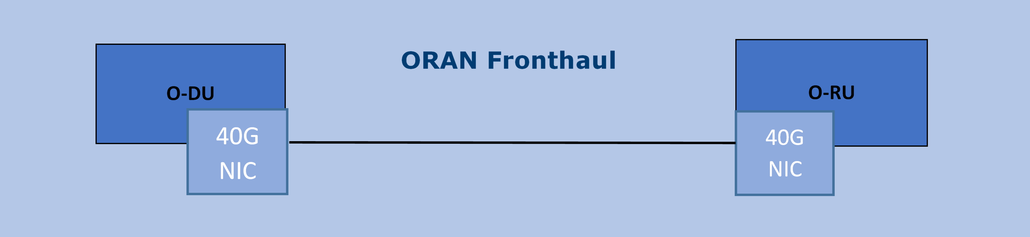
Figure 8. O-RAN Fronthaul Process
The O-RAN library provides support for transporting In-band and Quadrature (IQ) samples between the O-DU and O-RU within the O-RAN architecture based on functional split 7.2x. The library defines the O-RAN packet formats to be used to transport radio samples within Front Haul according to the O-RAN Fronthaul specification. refer to Table 2. It provides functionality for generating O-RAN packets, appending IQ samples in the packet payload, and extracting IQ samples from O-RAN packets.
Note: The F release version of the library supports U-plane and C-plane only. M-plane is not supported. It is ready to be used in the PTP synchronized environment.
Note: Regarding the clock model and synchronization topology, configurations C1 and C3 of the connection between O-DU and O-RU are the only configurations supported in this release of the O-RAN implementation.
Note: Quality of PTP synchronization with respect to S-plane of O-RAN Fronthaul requirements as defined for O-RU is out of the scope of this document. PTP primary and PTP secondary configuration are expected to satisfy only the O-DU side of requirements and provide the “best-effort” PTP primary for O-RU. This may or may not be sufficient for achieving the end to end system requirements of S-plane. Specialized dedicated NIC card with additional HW functionality might be required to achieve PTP primary functionality to satisfy O-RU precision requirements for RAN deployments scenarios.
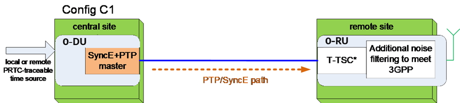
Figure 9. Configuration C1
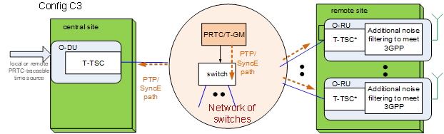
Figure 10. Configuration C3
Supported Feature Set
The O-RAN Fronthaul specification defines a list of mandatory functionalities.
Note: Not all features defined as Mandatory for O-DU are currently supported to a full extension. The following tables contain information on what is available and the level of validation performed for this release.
Note. Cells with a red background are listed as mandatory in the specification but not supported in this implementation of O-RAN.
Table 7. O-RAN Mandatory and Optional Feature Support
Category |
Feature |
O-DU Support |
Support |
|---|---|---|---|
RU Category |
Support for
CAT-A RU (up to
8 spatial
streams)
|
Mandatory |
Y |
Support for
CAT-A RU (> 8
spatial
streams)
|
Y |
||
Support for
CAT-B RU
(precoding in
RU)
|
Mandatory |
Y |
|
Beamforming |
Beam Index
based
|
Mandatory |
Y |
Real-time BF
Weights
|
Mandatory |
Y |
|
Real-Time
Beamforming
Attributes
|
N |
||
UE Channel Info |
N |
||
Bandwidth Saving |
Programmable
staticbitwidth
Fixed Point IQ
|
Mandatory |
Y |
Real-time
variable-bit
-width
|
Y |
||
Compressed IQ |
Y |
||
Block floating
point
compression
|
Y |
||
Block scaling
compression
|
N |
||
u-law
compression
|
N |
||
modulation
compression
|
Y |
||
beamspace
compression
|
Y |
||
Variable Bit
Width per
Channel (per
data section)
|
Y |
||
Static
configuration
of U-Plane IQ
format and
compression
header
|
N |
||
Use of symInc
flag to allow
multiple
symbols in a
C-Plane section
|
N |
||
Energy Saving |
Transmission
blanking
|
N |
|
O-DU - RU Timing |
Pre-configured
Transport Delay
Method
|
Mandatory |
Y |
Measured
Transport
Method (eCPRI
Msg 5)
|
N |
||
Synchronization |
G.8275.1 |
Mandatory |
Y (C3 only) |
G.8275.2 |
N |
||
GNSS based sync |
N |
||
SyncE |
N |
||
Transport Features |
L2 : Ethernet |
Mandatory |
Y |
L3 : IPv4, IPv6
(CUS Plane)
|
N |
||
QoS over
Fronthaul
|
Mandatory |
Y |
|
Prioritization
of different
U-plane traffic
types
|
N |
||
Support of
Jumbo Ethernet
frames
|
N |
||
eCPRI
|
Mandatory |
Y |
|
support of
eCPRI
concatenation
|
N |
||
IEEE 1914.3 |
N |
||
Application
fragmentation
|
Mandatory |
Y |
|
Transport
fragmentation
|
N |
||
Other |
LAA LBT O-DU
Congestion
Window mgmt
|
N |
|
LAA LBT RU
Congestion
Window mgm
|
N |
Details on the subset of O-RAN functionality implemented are shown in Table 8.
Level of Validation Specified as:
C: Completed code implementation for O-RAN Library
I: Integrated into Intel FlexRAN PHY
T: Tested end to end with O-RU
Table 8. Levels of Validation
Category |
Item |
Status |
C |
I |
T |
|
|---|---|---|---|---|---|---|
General |
Radio
access
technology
(LTE / NR)
|
NR/LTE |
N/A |
N/A |
N/A |
|
Nominal
sub-carrier
spacing
|
15
/30/120KHz
|
Y |
Y |
N |
||
FFT size |
512/1024
/2048/4096
|
Y |
Y |
N |
||
Channel
bandwidth
|
5/10
/20/100Mhz
|
Y |
Y |
N |
||
Number of
Cells
(Component
Carriers)
|
12 |
Y |
Y |
N |
||
RU
category
|
A, B |
Y |
Y |
N |
||
TDD Config |
Supported
/Flexible
|
Y |
Y |
N |
||
FDD
Support
|
Supported |
Y |
Y |
N |
||
Tx/Rx
switching
based on
‘data
Direction’
field of
C-plane
message
|
Supported |
Y |
Y |
N |
||
IP version
for
Management
traffic at
fronthaul
network
|
N/A |
N/A |
N/A |
N/A |
||
PRACH |
One Type 3
message
for all
repeated
PRACH
preambles
|
Supported |
Y |
Y |
N |
|
Type 3
message
per
repeated
PRACH
preambles
|
1 |
Y |
Y |
N |
||
timeOffset
including
cpLength
|
Supported |
Y |
Y |
N |
||
Supported |
Supported |
Y |
Y |
N |
||
PRACH
preamble
format/
index
number
(number of
occasions)
|
Supported |
Y |
Y |
N |
||
Delay
management
|
Network
delay
determination
|
Supported |
Y |
Y |
N |
|
lls-CU
timing
advance
type
|
Supported |
Y |
Y |
N |
||
Non-delay
managed
U-plane
traffic
|
Not
supported
|
N |
N |
N |
||
C/U-plane
Transport
|
Transport
encapsulation
(Ethernet/IP)
|
Ethernet |
Y |
Y |
N |
|
Jumbo
frames
|
Supported |
Y |
Y |
N |
||
Transport
header
(eCPRI/RoE)
|
eCPRI |
Y |
Y |
N |
||
IP version
when
Transport
header is
IP/UDP
|
N/A |
N/A |
N/A |
N/A |
||
eCPRI
Concatenation
when
Transport
header is
eCPRI
|
Not
supported
|
N |
N |
N |
||
eAxC ID
CU_Port_ID
bitwidth
|
4 * |
Y |
Y |
N |
||
eAxC ID
BandSector_ID
bitwidth
|
4 * |
Y |
Y |
N |
||
eAxC ID
CC_ID
bitwidth
|
4 * |
Y |
Y |
N |
||
eAxC ID
RU_Port_ID
bitwidth
|
4 * |
Y |
Y |
N |
||
Fragmentation |
Supported |
Y |
Y |
N |
||
Transport
prioritization
within
U-plane
|
N/A |
N |
N |
N |
||
Separation
of
C/U-plane
and
M-plane
|
Supported |
Y |
Y |
N |
||
Separation
of C-plane
and
U-plane
|
VLAN ID
|
Y |
Y |
N |
||
Max Number
of VLAN
per
physical
port
|
16 |
Y |
Y |
N |
||
Reception
Window
Monitoring
(Counters)
|
Rx_on_time |
Supported |
Y |
Y |
N |
|
Rx_early |
Supported |
N |
N |
N |
||
Rx_late |
Supported |
N |
N |
N |
||
Rx_corrupt |
Supported |
N |
N |
N |
||
Rx_pkt_dupl
|
Supported |
N |
N |
N |
||
Total_msgs_rcvd
|
Supported |
Y |
N |
N |
||
Beam-
forming
|
RU
beamforming
type
|
Index and
weights
|
Y |
Y |
N |
|
Beamforming
control
method
|
C-plane |
Y |
N |
N |
||
Number of
beams
|
No res-
strictions
|
Y |
Y |
N |
||
IQ
compre
ssion
|
U-plane
data
compression
method
|
Supported |
Y |
Y |
Y |
|
U-plane
data IQ
bitwidth
(Before /
After
compression)
|
BFP:
8,9,12,14
bits
Modulation
compression:
1,2,3,4 bits
|
Y |
Y |
Y |
||
Static
configuration
of U-plane
IQ format
and
compression
header
|
Supported |
N |
N |
N |
||
eCPRI
Header
Format
|
ecpriVersion
|
001b |
Y |
Y |
Y |
|
ecpriReserved
|
Supported |
Y |
Y |
Y |
||
ecpriCon
catenation
|
Not
supported
|
N |
N |
N |
||
ecpri
Message
|
U-plane |
Supported |
Y |
Y |
Y |
|
C-plane |
Supported |
Y |
Y |
Y |
||
Delay
measure
ment
|
Supported |
Y |
Y |
Y |
||
ecpri
Payload
(payload
size in
bytes)
|
Supported |
Y |
Y |
Y |
||
ecpriRtcid
/ecpriPcid
|
Supported |
Y |
Y |
Y |
||
ecpri
Seqid:
Sequence
ID
|
Supported |
Y |
Y |
Y |
||
ecpri
Seqid:
E bit
|
Supported |
Y |
Y |
Y |
||
ecpri
Seqid:
Sub
sequence
ID
|
Not
supported
|
N |
N |
N |
||
C-plane
Type
|
Section
Type 0
|
Not
supported
|
N |
N |
N |
|
Section
Type 1
|
Supported |
Y |
Y |
Y |
||
Section
Type 3
|
Supported |
Y |
Y |
Y |
||
Section
Type 5
|
Not
supported
|
N |
N |
N |
||
Section
Type 6
|
Not
supported
|
N |
N |
N |
||
Section
Type 7
|
Not
supported
|
N |
N |
N |
||
C-plane
Packet
Format
|
Coding
of Infor
mation
Elements
Appli
cation
Layer,
Common
|
data
Direction
(data
direction
(gNB
Tx/Rx))
|
Supported |
Y |
Y |
N |
payload
Version
(payload
version)
|
001b
|
Y |
Y |
N |
||
filter
Index
(filter
index)
|
Supported |
Y |
Y |
N |
||
frameId
(frame
iden
tifier)
|
Supported |
Y |
Y |
N |
||
subframeId
(subframe
iden
tifier)
|
Supported |
Y |
Y |
N |
||
slotId
(slot
iden
tifier)
|
Supported |
Y |
Y |
N |
||
start
Symbolid
(start
symbol
iden
tifier)
|
Supported |
Y |
Y |
N |
||
number
Ofsections
(number of
sections)
|
up to the
maximum
number of
PRBs
|
Y |
Y |
N |
||
section
Type
(section
type)
|
1 and 3
|
Y |
Y |
N |
||
udCompHdr
(user data
com
pression
header)
|
Supported |
Y |
Y |
N |
||
number
OfUEs
(number Of
UEs)
|
Not
supported
|
N |
N |
N |
||
timeOffset
(time
offset)
|
Supported |
Y |
Y |
N |
||
frame
Structure
(frame
structure)
|
mu=0,1,3 |
Y |
Y |
N |
||
cpLength
(cyclic
prefix
length)
|
Supported |
Y |
Y |
N |
||
Coding
of Infor
mation
Elements
Ap
plication
Layer,
Sections
|
sectionId
(section
iden
tifier)
|
Supported |
Y |
Y |
N |
|
rb
(resource
block
indicator)
|
0 |
Y |
Y |
N |
||
symInc
(symbol
number
increment
command)
|
0 or 1 |
Y |
Y |
N |
||
startPrbc
(starting
PRB of
control
section)
|
Supported |
Y |
Y |
N |
||
reMask
(resource
element
mask)
|
Supported |
Y |
Y |
N |
||
numPrbc
(number of
contiguous
PRBs per
control
section)
|
Supported |
Y |
Y |
N |
||
numSymbol
(number of
symbols)
|
Supported |
Y |
Y |
N |
||
ef
(extension
flag)
|
Supported |
Y |
Y |
N |
||
beamId
(beam
iden
tifier)
|
Support |
Y |
Y |
N |
||
ueId (UE
iden
tifier)
|
Not
supported
|
N |
N |
N |
||
freqOffset
(frequency
offset)
|
Supported |
Y |
Y |
N |
||
regulari
zation
Factor
(regulari
zation
Factor)
|
Not
supported
|
N |
N |
N |
||
ciIsample,
ciQsample
(channel
infor
mation
I and Q
values)
|
Not
supported
|
N |
N |
N |
||
laaMsgType
(LAA
message
type)
|
Not
supported
|
N |
N |
N |
||
laaMsgLen
(LAA
message
length)
|
Not
supported
|
N |
N |
N |
||
lbtHandle |
Not
supported
|
N |
N |
N |
||
lbtDefer
Factor
(listen
before
talk
defer
factor)
|
Not
supported
|
N |
N |
N |
||
lbtBack
offCounter
(listen
before
talk
backoff
counter)
|
Not
supported
|
N |
N |
N |
||
lbtOffset
(listen-
before
talk
offset)
|
Not
supported
|
N |
N |
N |
||
MCOT
(maximum
channel
occupancy
time)
|
Not
supported
|
N |
N |
N |
||
lbtMode
(LBT Mode)
|
Not
supported
|
N |
N |
N |
||
lbt
PdschRes
(LBT PDSCH
Result)
|
Not
supported
|
N |
N |
N |
||
sfStatus
(subframe
status)
|
Not
supported
|
N |
N |
N |
||
lbtDrsRes
(LBT DRS
Result)
|
Not
supported
|
N |
N |
N |
||
initial
PartialSF
(Initial
partial
SF)
|
Not
supported
|
N |
N |
N |
||
lbtBufErr
(LBT
Buffer
Error)
|
Not
supported
|
N |
N |
N |
||
sfnSf
(SFN/SF
End)
|
Not
supported
|
N |
N |
N |
||
lbt
CWConfig_H
(HARQ
Parameters
for
Congestion
Window
mana
gement)
|
Not
supported
|
N |
N |
N |
||
lbt
CWConfig_T
(TB
Parameters
for
Congestion
Window
mana
gement)
|
Not
supported
|
N |
N |
N |
||
lbtTr
afficClass
(Traffic
class
priority
for
Congestion
Window
mana
gement)
|
Not
supported
|
N |
N |
N |
||
lbtCWR_Rst
(Noti
cation
about
packet
reception
successful
or not)
|
Not
supported
|
N |
N |
N |
||
reserved
(reserved
for future
use)
|
0 |
N |
N |
N |
||
Section
Exten
sion
Commands
|
||||||
extType
(extension
type)
|
Supported |
Y |
Y |
N |
||
ef
(extension
flag)
|
Supported |
Y |
Y |
N |
||
extLen
(extension
length)
|
Supported |
Y |
Y |
N |
||
Coding of
Infor
mation
Elements –
Appli
cation
Layer,
Section
Exten
sions
|
||||||
Ext
Type=1:
Beam
forming
Weights
Exten*
*sion
Type
|
bfw
CompHdr
(beam
forming
weight
compre
ssion
header)
|
Supported |
Y |
Y |
N |
|
bf
wCompParam
(beam
forming
weight
compre
ssion
parameter)
|
Supported |
Y |
Y |
N |
||
bfwl
(beam
forming
weight
in-phase
value)
|
Supported |
Y |
Y |
N |
||
bfwQ
(beam
forming
weight
quadrature
value)
|
Supported |
Y |
Y |
N |
||
ExtType
=2:
Beam
forming
Attribu
tes
Exten
sion
Type
|
bfaCompHdr
(beamforming
attributes
compre
ssion
header)
|
Supported |
Y |
N |
N |
|
bfAzPt
(beam
forming
azimuth
pointing
parameter)
|
Supported |
Y |
N |
N |
||
bfZePt
(beam
forming
zenith
pointing
parameter)
|
Supported |
Y |
N |
N |
||
bfAz3dd
(beam
forming
azimuth
beamwidth
parameter)
|
Supported |
Y |
N |
N |
||
bfZe3dd
(beam
forming
zenith
beamwidth
parameter)
|
Supported |
Y |
N |
N |
||
bfAzSl
(beam
forming
azimuth
sidelobe
parameter)
|
Supported |
Y |
N |
N |
||
bfZeSl
(beam
forming
zenith
sidelobe
parameter)
|
Supported |
Y |
N |
N |
||
zero-
padding
|
Supported |
Y |
N |
N |
||
ExtType
=3:
DL
Preco
ding
Exten
sion
Type
|
code
bookIndex
(precoder
codebook
used for
trans
mission
|
Supported |
Y |
N |
N |
|
layerID
(Layer ID
for DL
trans
mission)
|
Supported |
Y |
N |
N |
||
txScheme
(trans
mission
scheme)
|
Supported |
Y |
N |
N |
||
numLayers
(number of
layers
used for
DL
trans
mission)
|
Supported |
Y |
N |
N |
||
crsReMask
(CRS
resource
element
mask)
|
Supported |
Y |
N |
N |
||
crs
SyumINum
(CRS
symbol
number
indi
cation)
|
Supported |
Y |
N |
N |
||
crsShift
(crsShift
used for
DL
trans
mission)
|
Supported |
Y |
N |
N |
||
beamIdAP1
(beam id
to be used
for
antenna
port 1)
|
Supported |
Y |
N |
N |
||
beamIdAP2
(beam id
to be used
for
antenna
port 2)
|
Supported |
Y |
N |
N |
||
beamIdAP3
(beam id
to be used
for
antenna
port 3)
|
Supported |
Y |
N |
N |
||
ExtType
=4:
Modula
tion
Compre
ssion
Parame
ters
Exten
sion
Type
|
csf
(cons
tellation
shift
flag)
|
Supported
|
Y |
Y |
N |
|
mod
CompScaler
(
modulation
compre
ssion
scaler
value)
|
Supported
|
Y |
Y |
N |
||
ExtType
=5:
Modula
tion
Compre
ssion
Additio
Parame
ters
Exten
sion
Type*
|
mcScale
ReMask
(
modulation
compre
ssion
power
RE
mask)
|
Supported
|
Y |
N |
N |
|
csf
(cons
tellation
shift
flag)
|
Supported
|
Y |
N |
N |
||
mcScale
Offset
(scaling
value for
modulation
compre
ssion)
|
Supported |
Y |
N |
N |
||
E
xtType=6:
Non-con
tiguous
PRB
alloca
tion in
time and
frequen
cy domain
|
rbgSize
(resource
block
group
size)
|
Supported |
Y |
N |
N |
|
rbgMask
(resource
block
group bit
mask)
|
Supported |
Y |
N |
N |
||
symbol
Mask
(symbol
bit mask)
|
Supported |
Y |
N |
N |
||
Ext
Type=10:
Section
des*
*cription
for gro*
*up
configu*
*ration of
multiple
ports
|
beam
GroupType
|
Supported |
Y |
N |
N |
|
numPortc |
Supported |
Y |
N |
N |
||
Ext
Type=11:
Flexible
Beam
forming
Weights
Exten
sion
Type
|
b
fwCompHdr
(beam
forming
weight
compre
ssion
header)
|
Supported |
Y |
Y |
N |
|
bfw
CompParam
for PRB
bundle x
(beam
forming
weight
compre
ssion
parameter)
|
Supported |
Y |
Y |
N |
||
numBundPrb
(Number
of
bundled
PRBs per
beam
forming
weights)
|
Supported |
Y |
Y |
N |
||
bfwI
(beam
forming
weight
in-phase
value)
|
Supported |
Y |
Y |
N |
||
bfwQ
(beam
forming
weight
quadra
ture
value)
|
Supported |
Y |
Y |
N |
||
disable
BFWs
(disable
beam
forming
weights)
|
Supported |
Y |
Y |
N |
||
RAD
(Reset
After PRB
Discon
tinuity)
|
Supported |
Y |
Y |
N |
||
U-plane
Packet
Format
|
data
Direction
(data
direction
(gNB
Tx/Rx))
|
Supported |
Y |
Y |
Y |
|
payload
Version
(payload
version)
|
001b |
Y |
Y |
Y |
||
filter
Index
(filter
index)
|
Supported |
Y |
Y |
Y |
||
frameId
(frame
iden
tifier)
|
Supported |
Y |
Y |
Y |
||
subframeId
(subframe
iden
tifier)
|
Supported |
Y |
Y |
Y |
||
slotId
(slot
iden
tifier)
|
Supported |
Y |
Y |
Y |
||
symbolId
(symbol
iden
tifier)
|
Supported |
Y |
Y |
Y |
||
sectionId
(section
iden
tifier)
|
Supported |
Y |
Y |
Y |
||
rb
(resource
block
indicator)
|
0 |
Y |
Y |
Y |
||
symInc
(symbol
number
increment
command)
|
0 |
Y |
Y |
Y |
||
startPrbu
(startingPRB
of user
plane
section)
|
Supported |
Y |
Y |
Y |
||
numPrbu
(number of
PRBs per
user plane
section)
|
Supported |
Y |
Y |
Y |
||
udCompHdr
(user data
com
pression
header)
|
Supported |
Y |
Y |
N |
||
reserved
(reserved
for future
use)
|
0 |
Y |
Y |
Y |
||
udCompParam
(user data
compre
ssion
parameter)
|
Supported |
Y |
Y |
N |
||
iSample
(in-phase
sample)
|
16 |
Y |
Y |
Y |
||
qSample
(
quadrature
sample)
|
16 |
Y |
Y |
Y |
||
S-plane |
Topology
confi
guration:
C1
|
Supported |
N |
N |
N |
|
Topology
confi
guration:
C2
|
Supported |
N |
N |
N |
||
Topology
confi
guration:
C3
|
Supported |
Y |
Y |
Y |
||
Topology
confi
guration:
C4
|
Supported |
N |
N |
N |
||
PTP |
Full
Timing
Support
(G.8275.1)
|
Supported |
Y |
Y |
N |
|
M-plane |
Not
supported
|
N |
N |
N |
||
* The bit width of each component in eAxC ID can be configurable.
Transport Layer
O-RAN Fronthaul data can be transported over Ethernet or IPv4/IPv6. In the current implementation, the O-RAN library supports only Ethernet with VLAN.

Figure 11. Native Ethernet Frame with VLAN
Standard DPDK routines are used to perform Transport Layer functionality.
VLAN tag functionality is offloaded to NIC as per the configuration of VF (refer to Appendix A, Setup Configuration).
The transport header is defined in the O-RAN Fronthaul specification based on the eCPRI specification, Refer to Table 2.
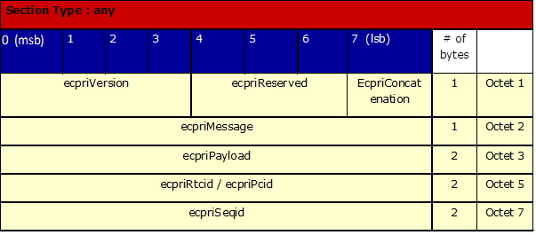
Figure 12. eCPRI Header Field Definitions
Only ECPRI_IQ_DATA = 0x00 , ECPRI_RT_CONTROL_DATA= 0x02 and ECPRI_DELAY_MEASUREMENT message types are supported.
For one-way delay measurements the eCPRI Header Field Definitions are the same as above until the ecpriPayload. The one-delay measurement message format is shown in the next figure.
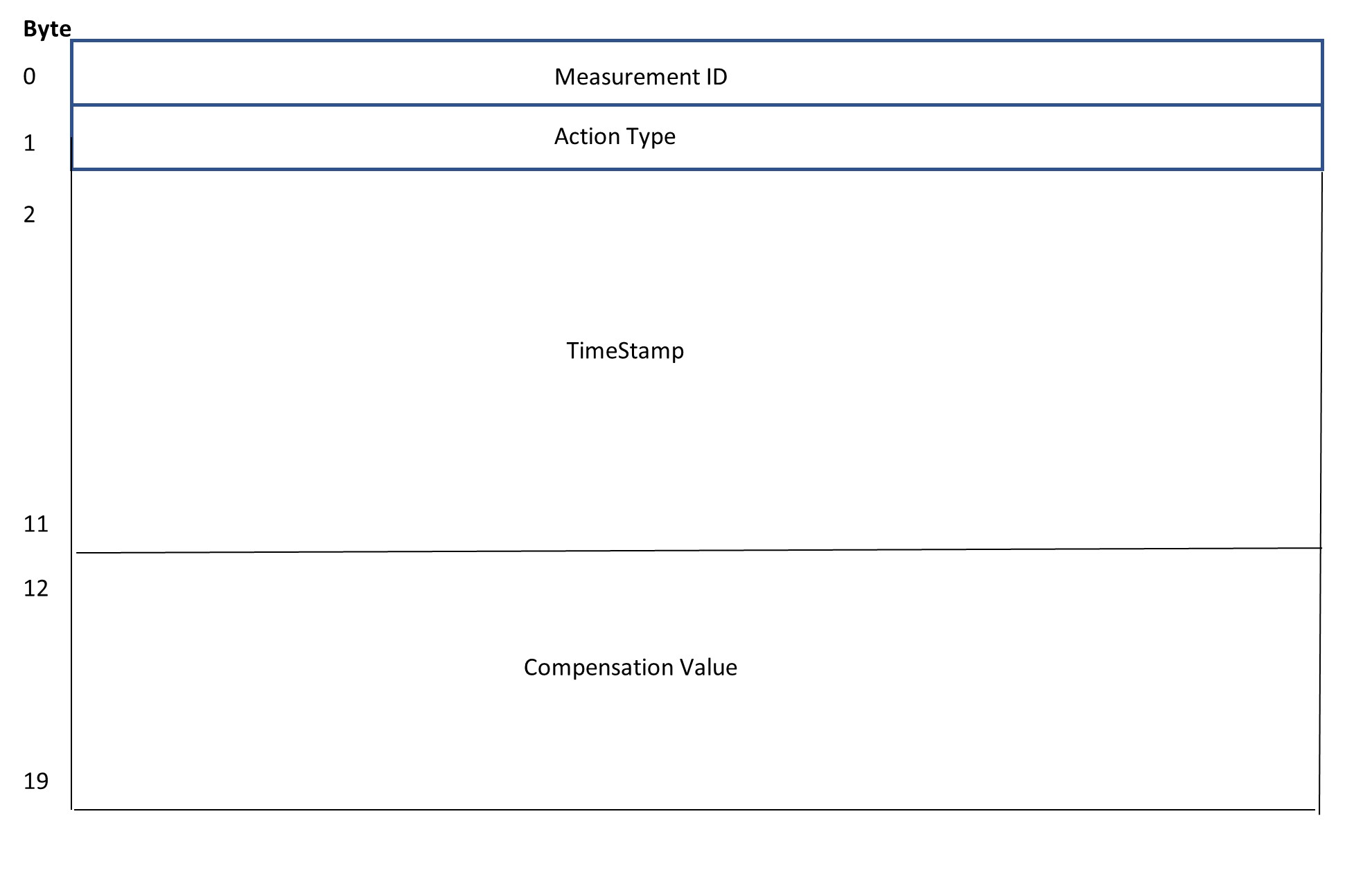
Figure 13. ecpri one-way delay measurement message
In addition, for the eCPRI one-delay measurement message there is a requirement of dummy bytes insertion so the overall ethernet frame has at least 64 bytes.
The measurement ID is a one-byte value used by the sender of the request to distinguish the response received between different measurements.
The action type is a one-byte value defined in Table 8 of the eCPRI Specification V2.0.
Action Type 0x00 corresponds to a Request
Action Type 0x01 corresponds to a Request with Follow Up
Both values are used by an eCPRI node to initiate a one-way delay measurement in the direction of its own node to another node.
Action Type 0x02 corresponds to a Response
Action Type 0x03 is a Remote Request
Action Type 0x04 is a Remote Request with Follow Up
Values 0x03 and 0x04 are used when an eCPRI node needs to know the one-way delay from another node to itself.
Action Type 0x05 is the Follow_Up message.
The timestamp uses the IEEE-1588 Timestamp format with 8 bytes for the seconds part and 4 bytes for the nanoseconds part. The timestamp is a positive time with respect to the epoch.
The compensation value is used with Action Types 0x00 (Request), 0x02 (Response) or 0x05 (Follow_up) for all others this field contains zeros. This value is the compensation time measured in nanoseconds and multiplied by 216 and follows the format for the correctionField in the common message header specified by the IEE 1588-2008 clause 13.3.
Handling of ecpriRtcid/ecpriPcid Bit field size is configurable and can be defined on the initialization stage of the O-RAN library.
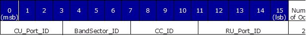
Figure 14. Bit Allocations of ecpriRtcid/ecpriPcid
For ecpriSeqid only, the support for a sequence number is implemented. The following number is not supported.
Comments in the source code can be used to see more information on the implementation specifics of handling this field.
U-plane
The following diagrams show O-RAN packet protocols’ headers and data arrangement with and without compression support.
O-RAN packet meant for traffic with compression enabled has the Compression Header added after each Application Header. According to O-RAN Fronthaul’s specification (Refer to Table 2), the Compression Header is part of a repeated Section Application Header. In the O-RAN library implementation,the header is implemented as a separate structure, following the Application Section Header. As a result, the Compression Header is not included in the O-RAN packet, if compression is not used.
Figure 15 shows the components of an ORAN packet.
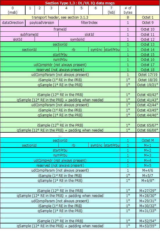
Figure 15. O-RAN Packet Components
Radio Application Header
The next header is a common header used for time reference.
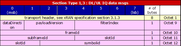
Figure 16. Radio Application Header
The radio application header specific field values are implemented as follows:
filterIndex = 0
frameId = [0:99]
subframeId = [0:9]
slotId = [0:7]
symbolId = [0:13]
Data Section Application Data Header
The Common Radio Application Header is followed by the Application Header that is repeated for each Data Section within the eCPRI message. The relevant section of the O-RAN packet is shown in color.
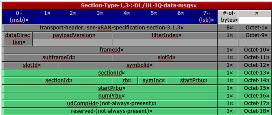
Figure 17. Data Section Application Data Header
A single section is used per one Ethernet packet with IQ samples startPrbu is equal to 0 and numPrbu is equal to the number of RBs used:
rb field is not used (value 0).
symInc is not used (value 0)
Data Payload
An O-RAN packet data payload contains several PRBs. Each PRB is built of 12 IQ samples. Flexible IQ bit width is supported. If compression is enabled, udCompParam is included in the data payload. The data section is shown in color.
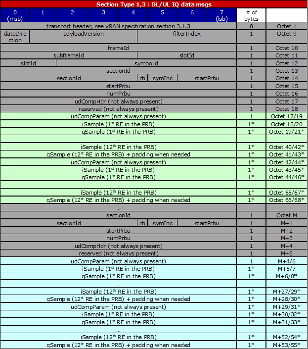
Figure 18. Data Payload
C-plane
C-Plane messages are encapsulated using a two-layered header approach. The first layer consists of an eCPRI standard header, including corresponding fields used to indicate the message type, while the second layer is an application layer, including necessary fields for control and synchronization. Within the application layer, a “section” defines the characteristics of U-plane data to be transferred or received from a beam with one pattern id. In general, the transport header, application header, and sections are all intended to be aligned on 4-byte boundaries and are transmitted in “network byte order” meaning the most significant byte of a multi-byte parameter is transmitted first.
Table 9 is a list of sections currently supported.
Table 9. Section Types
Section Type |
Target Scenario |
Remarks |
0 |
Unused Resource Blocks
or symbols in Downlink
or Uplink
|
Not supported |
1 |
Most DL/UL radio
channels
|
Supported |
2 |
reserved for future use |
N/A |
3 |
PRACH and
mixed-numerology
channels
|
Only PRACH is supported.
Mixed numerology is not
supported.
|
4 |
Reserved for future use |
Not supported |
5 |
UE scheduling
information (UE-ID
assignment to section)
|
Not supported |
6 |
Channel information |
Not supported |
7 |
LAA |
Not supported |
8-255 |
Reserved for future use |
N/A |
Section extensions are not supported in this release.
The definition of the C-Plane packet can be found lib/api/xran_pkt_cp.h, and the fields are appropriately re-ordered in order to apply the conversion of network byte order after setting values. The comments in the source code of O-RAN lib can be used to see more information on the implementation specifics of handling sections as well as particular fields. Additional changes may be needed on the C-plane to perform IOT with an O-RU depending on the scenario.
Ethernet Header
Refer to Figure 11.
eCPRI Header
Refer to Figure 12.
This header is defined as the structure of xran_ecpri_hdr in lib/api/xran_pkt.h.
Radio Application Common Header
The Radio Application Common Header is used for time reference. Its structure is shown in Figure 19.
Figure 19. Radio Application Common Header
This header is defined as the structure of xran_cp_radioapp_common_header in lib/api/xran_pkt_cp.h.
Note: The payload version in this header is fixed to XRAN_PAYLOAD_VER (defined as 1) in this release.
Section Type 0 Structure
Figure 20 describes the structure of Section Type 0.
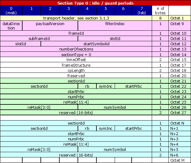
Figure 20. Section Type 0 Structure
In Figure 19 through Figure 23, the color yellow means it is a transport header; the color pink is the radio application header; others are repeated sections.
Section Type 1 Structure
Figure 21 describes the structure of Section Type 1.
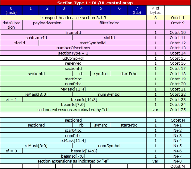
Figure 21. Section Type 1 Structure
Section Type 1 message has two additional parameters in addition to radio application common header:
udCompHdr : defined as the structure of xran_radioapp_udComp_header
reserved : fixed by zero
Section type 1 is defined as the structure of xran_cp_radioapp_section1, and this part can be repeated to have multiple sections.
Whole section type 1 message can be described in this summary:
xran_cp_radioapp_common_header |
|---|
xran_cp_radioapp_section1_header |
xran_cp_radioapp_section1 |
…… |
xran_cp_radioapp_section1 |
Note: Even though the API function can support composing multiple sections in a C-Plane message, the current implementation is limited to composins a single section per C-Plane message.
Section Type 3 Structure
Figure 22 describes the structure of Section Type 3.
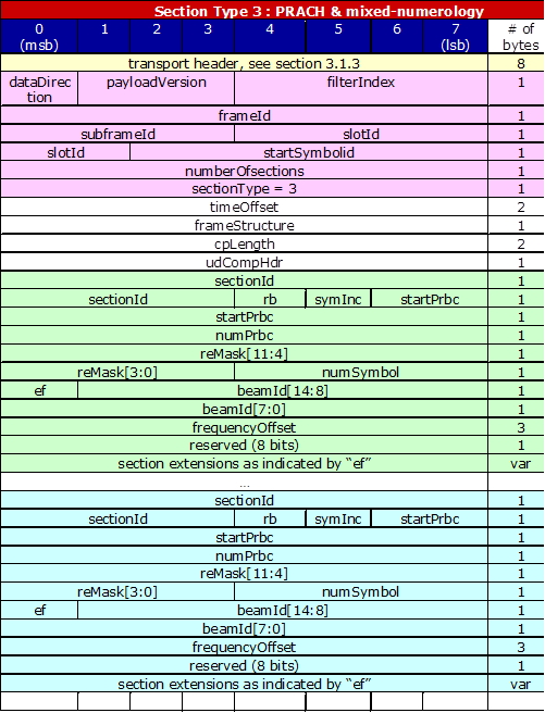
Figure 22. Section Type 3 Structure
Section Type 3 message has below four additional parameters in addition to radio application common header.
timeOffset
frameStructure: defined as the structure of xran_cp_radioapp_frameStructure
cpLength
udCompHdr: defined as the structure of xran_radioapp_udComp_header
Section Type 3 is defined as the structure of xran_cp_radioapp_section3 and this part can be repeated to have multiple sections.
Whole section type 3 message can be described in this summary:
xran_cp_radioapp_common_header |
|---|
xran_cp_radioapp_section3_header |
xran_cp_radioapp_section3 |
…… |
xran_cp_radioapp_section3 |
Section Type 5 Structure
Figure 23 describes the structure of Section Type 5.
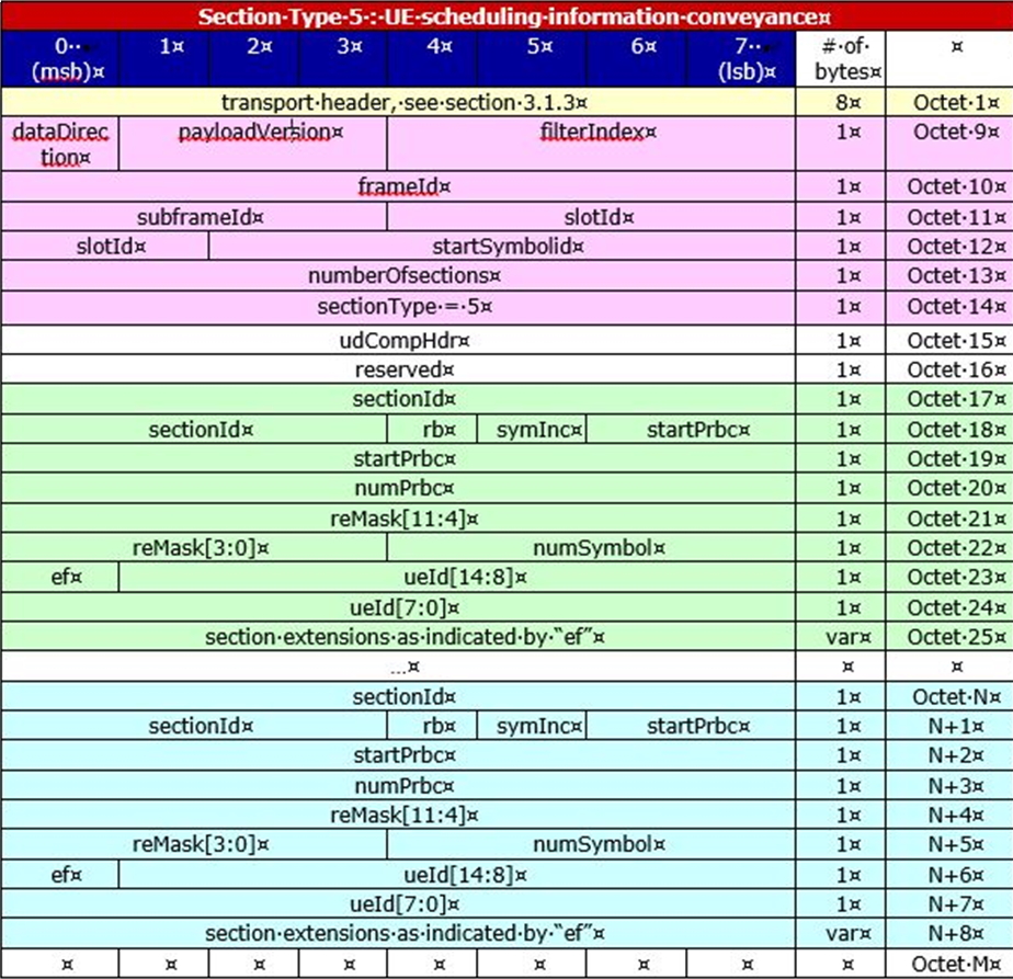
Figure 23. Section Type 5 Structure
Section Type 6 Structure
Figure 24 describes the structure of Section Type 6.
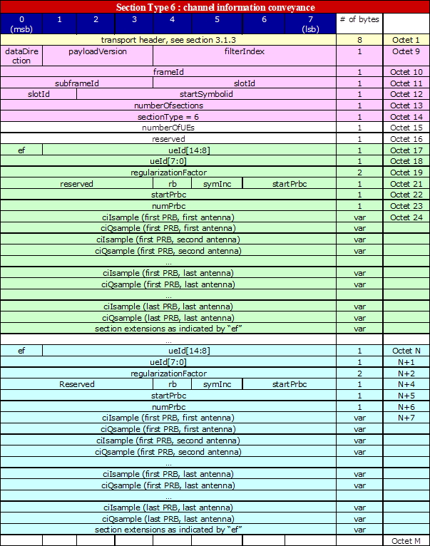
Figure 24. Section Type 6 Structure