O-RAN Library Design
The O-RAN Library consists of multiple modules where different functionality is encapsulated. The complete list of all *.c and *.h files, as well as Makefile for O-RAN (aka FHI Lib)f release is:
├── app
│ ├── dpdk.sh
│ ├── gen_test.m
│ ├── Makefile
│ ├── ifft_in.txt
│ ├── run_o_du.sh
│ ├── run_o_ru.sh
│ ├── src
│ │ ├── app_bbu_main.c
│ │ ├── app_bbu_pool.c
│ │ ├── app_bbu_pool.h
│ │ ├── app_dl_bbu_pool_tasks.c
│ │ ├── app_io_fh_xran.c
│ │ ├── app_io_fh_xran.h
│ │ ├── app_profile_xran.c
│ │ ├── app_profile_xran.h
│ │ ├── app_ul_bbu_pool_tasks.c
│ │ ├── aux_line.c
│ │ ├── aux_line.h
│ │ ├── common.c
│ │ ├── common.h
│ │ ├── config.c
│ │ ├── config.h
│ │ ├── debug.h
│ │ ├── ebbu_pool_cfg.c
│ │ ├── ebbu_pool_cfg.h
│ │ ├── sample-app.c
│ │ └── xran_mlog_task_id.h
│ └── usecase
│ ├── cat_a
│ ├── cat_b
│ ├── dss
│ ├── lte_a
│ ├── lte_b
├── build.sh
├── lib
│ ├── api
│ │ ├── xran_compression.h
│ │ ├── xran_compression.hpp
│ │ ├── xran_cp_api.h
│ │ ├── xran_ecpri_owd_measurements.h
│ │ ├── xran_fh_o_du.h
│ │ ├── xran_fh_o_ru.h
│ │ ├── xran_lib_mlog_tasks_id.h
│ │ ├── xran_mlog_lnx.h
│ │ ├── xran_pkt_cp.h
│ │ ├── xran_pkt.h
│ │ ├── xran_pkt_up.h
│ │ ├── xran_sync_api.h
│ │ ├── xran_timer.h
│ │ ├── xran_transport.h
│ │ └── xran_up_api.h
│ ├── ethernet
│ │ ├── ethdi.c
│ │ ├── ethdi.h
│ │ ├── ethernet.c
│ │ └── ethernet.h
│ ├── Makefile
│ └── src
│ ├── xran_bfp_byte_packing_utils.hpp
│ ├── xran_bfp_cplane8.cpp
│ ├── xran_bfp_cplane8_snc.cpp
│ ├── xran_bfp_cplane16.cpp
│ ├── xran_bfp_cplane16_snc.cpp
│ ├── xran_bfp_cplane32.cpp
│ ├── xran_bfp_cplane32_snc.cpp
│ ├── xran_bfp_cplane64.cpp
│ ├── xran_bfp_cplane64_snc.cpp
│ ├── xran_bfp_ref.cpp
│ ├── xran_bfp_uplane.cpp
│ ├── xran_bfp_uplane_9b16rb.cpp
│ ├── xran_bfp_uplane_snc.cpp
│ ├── xran_bfp_utils.hpp
│ ├── xran_cb_proc.c
│ ├── xran_cb_proc.h
│ ├── xran_common.c
│ ├── xran_common.h
│ ├── xran_compression.cpp
│ ├── xran_compression_snc.cpp
│ ├── xran_cp_api.c
│ ├── xran_cp_proc.c
│ ├── xran_cp_proc.h
│ ├── xran_delay_measurement.c
│ ├── xran_dev.c
│ ├── xran_dev.h
│ ├── xran_frame_struct.c
│ ├── xran_frame_struct.h
│ ├── xran_main.c
│ ├── xran_main.h
│ ├── xran_mem_mgr.c
│ ├── xran_mem_mgr.h
│ ├── xran_mod_compression.cpp
│ ├── xran_mod_compression.h
│ ├── xran_prach_cfg.h
│ ├── xran_printf.h
│ ├── xran_rx_proc.c
│ ├── xran_rx_proc.h
│ ├── xran_sync_api.c
│ ├── xran_timer.c
│ ├── xran_transport.c
│ ├── xran_tx_proc.c
│ ├── xran_tx_proc.h
│ ├── xran_ul_tables.c
│ └── xran_up_api.c
└── test
├── common
│ ├── common.cpp
│ ├── common.hpp
│ ├── common_typedef_xran.h
│ ├── json.hpp
│ ├── MIT_License.txt
│ ├── xranlib_unit_test_main.cc
│ └── xran_lib_wrap.hpp
├── master.py
├── readme.txt
└── test_xran
├── c_plane_tests.cc
├── chain_tests.cc
├── compander_functional.cc
├── conf.json
├── init_sys_functional.cc
├── Makefile
├── mod_compression_unit_test.cc
├── prach_functional.cc
├── prach_performance.cc
├── unittests.cc
└── u_plane_functional.cc
├── u_plane_performance.cc
General Introduction
The O-RAN FHI Library functionality is broken down into two main sections:
O-RAN specific packet handling (src)
Ethernet and supporting functionality (ethernet)
External functions and structures are available via a set of header files in the API folder.
This library depends on DPDK primitives to perform Ethernet networking in user space, including initialization and control of Ethernet ports. Ethernet ports are expected to be SRIOV virtual functions (VF) but also can be physical functions (PF) as well
This library is expected to be included in the project via xran_fh_o_du.h, statically compiled and linked with the L1 application as well as DPDK libraries. The O-RAN packet processing-specific functionality is encapsulated into this library and not exposed to the rest of the 5G NR pipeline.
This way, O-RAN specific changes are decoupled from the L1 pipeline. As a result, the design and implementation of the 5G L1 pipeline code and O-RAN FHI library can be done in parallel, provided the defined interface is not modified.
Ethernet consists of two modules:
Ethernet implements O-RAN specific HW Ethernet initialization, close, send and receive
ethdi provides Ethernet level software primitives to handle O-RAN packet exchange
The O-RAN layer implements the next set of functionalities:
Common code specific for both C-plane and U-plane as well as TX and RX
Implementation of C-plane API available within the library and externally
The primary function where general library initialization and configuration performed
Module to provide the status of PTP synchronization
Timing module where system time is polled
eCPRI specific transport layer functions
APIs to handle U-plane packets
A set of utility modules for debugging (printf) and data tables are included as well.
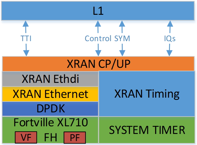
Figure 25. Illustration of O-RAN Sublayers
A detailed description of functions and input/output arguments, as well as key data structures, can be found in the Doxygen file for the FlexRAN 5G NR release, Refer to Table 2. In this document, supplemental information is provided for the overall design and implementation assumptions.(Available only outside of the Community Version)
Initialization and Close
An example of the initialization sequence can be found in the sample application code. It consists of the following steps:
1.Setup structure struct xran_fh_init according to configuration.
2.Call xran_init() to instantiate the O-RAN lib memory model and threads. The function returns a pointer to O-RAN handle which is used for consecutive configuration functions.
3.Initialize memory buffers used for L1 and O-RAN exchange of information.
4.Assign callback functions for (one) TTI event and for the reception of half of the slot of symbols (7 symbols) and Full slot of symbols 14 symbols).
5.Call xran_open() to initialize PRACH configuration, initialize DPDK, and launch xRAN timing thread,
6.Call xran_start() to start processing O-RAN packets for DL and UL.
After this is complete 5G L1 runs with O-RAN Front haul interface. During run time for every TTI event, the corresponding call back is called. For packet reception on UL direction, the corresponding call back is called. OTA time information such as frame id, subframe id, and slot id can be obtained as result synchronization of the L1 pipeline to GPS time is performed.
To stop and close the interface, perform this sequence of steps:
1.Call xran_stop() to stop the processing of DL and UL
2.Call xran_close() to remove usage of xRAN resources
3.Call xran_mm_destroy() to destroy memory management subsystem
After this session is complete, a restart of the full L1 application is required. The current version of the library does not support multiple sessions without a restart of the full L1 application.
Configuration
The O-RAN library configuration is provided in the set of structures, such as struct xran_fh_init and struct xran_fh_config. The sample application gives an example of a test configuration used for LTE and 5GNR mmWave and Sub 6. Sample application folder /app/usecase/ contains set of examples for different Radio Access technology (LTE|5G NR), different category (A|B) and list of numerologies (0,1,3) and list of bandwidths (5,10,20,100Mhz).
Note: Some configuration options are not used in the f release and are reserved for future use.
The following options are available:
Structure struct xran_fh_init:
Number of CC and corresponding settings for each
Core allocation for O-RAN
Ethernet port allocation
O-DU and RU Ethernet Mac address
Timing constraints of O-DU and 0-RU
Debug features
Structure struct xran_fh_config:
Number of eAxC
TTI Callback function and parameters
PRACH 5G NR specific settings
TDD frame configuration
BBU specific configuration
RU specific configuration
From an implementation perspective:
The xran_init() performs init of the O-RAN FHI library and interface according to struct xran_fh_init information as per the start of application configuration:
Init DPDK with corresponding networking ports and core assignment
Init mbuf pools
Init DPDK timers and DPDK rings for internal packet processing
Instantiates ORAH FH thread doing
Timing processing (xran_timing_source_thread())
ETH PMD (process_dpdk_io())
IO XRAN-PHY exchange (ring_processing_func())
xran_open() performs additional configuration as per run scenario:
PRACH configuration
C-plane initialization
The Function xran_close() performs free of resources and allows potential restart of front haul interface with a different scenario.
Start/Stop
The Functions xran_start()/xran_stop() enable/disable packet processing for both DL and UL. This triggers execution of callbacks into the L1 application.
Data Exchange
Exchange of IQ samples, as well as C-plane specific information, is performed using a set of buffers allocated by xRAN library from DPDK memory and shared with the l1 application. Buffers are allocated as a standard mbuf structure, and DPDK pools are used to manage the allocation and free resources. Shared buffers are allocated at the init stage and are expected to be reused within 80 TTIs (10 ms).
The O-RAN protocol requires U-plane IQ data to be transferred in network byte order, and the L1 application handles IQ sample data in CPU byte order, requiring a swap. The PHY BBU pooling tasks perform copy and byte order swap during packet processing.
C-plane Information Settings
The interface between the O-RAN library and PHY is defined via struct xran_prb_map and similar to the data plane. The same mbuf memory is used to allocate memory map of PRBs for each TTI.:
/*\* Beamforming waights for single stream for each PRBs given number of
Antenna elements \*/
struct xran_cp_bf_weight{

int16_t nAntElmTRx; /**< num TRX for this allocation \*/

int16_t ext_section_sz; /**< extType section size \*/

int8_t\* p_ext_start; /**< pointer to start of buffer for full C-plane
packet \*/

int8_t\* p_ext_section; /**< pointer to form extType \*/

/\* For ext 11 \*/

uint8_t bfwCompMeth; /\* Compression Method for BFW \*/

uint8_t bfwIqWidth; /\* Bitwidth of BFW \*/

uint8_t numSetBFWs; /\* Total number of beam forming weights set (L) \*/

uint8_t numBundPrb; /\* The number of bundled PRBs, 0 means to use ext1
\*/

uint8_t RAD;

uint8_t disableBFWs;

int16_t maxExtBufSize; /\* Maximum space of external buffer \*/

struct xran_ext11_bfw_info bfw[XRAN_MAX_SET_BFWS]

};

/*\* PRB element structure \*/

struct xran_prb_elm {

int16_t nRBStart; /**< start RB of RB allocation \*/

int16_t nRBSize; /**< number of RBs used \*/

int16_t nStartSymb; /**< start symbol ID \*/

int16_t numSymb; /**< number of symbols \*/

int16_t nBeamIndex; /**< beam index for given PRB \*/

int16_t bf_weight_update; /*\* need to update beam weights or not \*/

int16_t compMethod; /**< compression index for given PRB \*/

int16_t iqWidth; /**< compression bit width for given PRB \*/

uint16_t ScaleFactor; /**< scale factor for modulation compression \*/

int16_t reMask; /**< 12-bit RE Mask for modulation compression \*/

int16_t BeamFormingType; /**< index based, weights based or attribute
based beam forming*/

int16_t nSecDesc[XRAN_NUM_OF_SYMBOL_PER_SLOT]; /**< number of section
descriptors per symbol \*/

struct xran_section_desc \*
p_sec_desc[XRAN_NUM_OF_SYMBOL_PER_SLOT][XRAN_MAX_FRAGMENT]; /**< section
desctiptors to U-plane data given RBs \*/

struct xran_cp_bf_weight bf_weight; /**< beam forming information
relevant for given RBs \*/

union {

struct xran_cp_bf_attribute bf_attribute;

struct xran_cp_bf_precoding bf_precoding;

};

};

/*\* PRB map structure \*/

struct xran_prb_map {

uint8_t dir; /**< DL or UL direction \*/

uint8_t xran_port; /**< O-RAN id of given RU [0-(XRAN_PORTS_NUM-1)] \*/

uint16_t band_id; /**< O-RAN band id \*/

uint16_t cc_id; /**< component carrier id [0 - (XRAN_MAX_SECTOR_NR-1)]
\*/

uint16_t ru_port_id; /**< RU device antenna port id [0 -
(XRAN_MAX_ANTENNA_NR-1) \*/

uint16_t tti_id; /**< O-RAN slot id [0 - (max tti-1)] \*/

uint8_t start_sym_id; /**< start symbol Id [0-13] \*/

uint32_t nPrbElm; /**< total number of PRB elements for given map [0-
(XRAN_MAX_SECTIONS_PER_SLOT-1)] \*/

struct xran_prb_elm prbMap[XRAN_MAX_SECTIONS_PER_SLOT];

};
C-plane sections are expected to be provided by the L1 pipeline. If 100% of the RBs are used they are always allocated as a single element RB map, that is expected to be allocated across all symbols. Dynamic RB allocation is performed based on C-plane configuration.
The O-RAN library will require that the content of the PRB map should be sorted in increasing order of PRB first and then symbols.
Memory Management
Memory used for the exchange of IQ data as well as control information, is controlled by the O-RAN library. L1 application at the init stage performs:
init memory management subsystem
init buffer management subsystem (via DPDK pools)
allocate buffers (mbuf) for each CC, antenna, symbol, and direction (DL, UL, PRACH) for XRAN_N_FE_BUF_LEN TTIs.
buffers are reused for every XRAN_N_FE_BUF_LEN TTIs
After the session is completed, the application can free buffers and destroy the memory management subsystem.
From an implementation perspective, the O-RAN library uses a standard mbuf primitive and allocates a pool of buffers for each sector. This function is performed using rte_pktmbuf_pool_create(), rte_pktmbuf_alloc(), and rte_pktmbuf_append() to allocate one buffer per symbol for the mmWave case. More information on mbuf and DPDK pools can be found in the DPDK documentation.
In the current implementation, mbuf, the number of buffers shared with the L1 application is the same number of buffers used to send to and receive from the Ethernet port. Memory copy operations are not required if the packet size is smaller than or equal to MTU. Future versions of the O-RAN library are required to remove the memory copy requirement for packets where the size larger than MTU.
External Interface Memory
The O-RAN library header file defines a set of structures to simplify access to memory buffers used for IQ data.::
struct xran_flat_buffer {

   uint32_t nElementLenInBytes;

   uint32_t nNumberOfElements;

   uint32_t nOffsetInBytes;

   uint32_t nIsPhyAddr;

   uint8_t \*pData;

   void \*pCtrl;

};

struct xran_buffer_list {

   uint32_t nNumBuffers;

   struct xran_flat_buffer \*pBuffers;

   void \*pUserData;

   void \*pPrivateMetaData;

};

struct xran_io_buf_ctrl {

/\* -1-this subframe is not used in current frame format

0-this subframe can be transmitted, i.e., data is ready

1-this subframe is waiting transmission, i.e., data is not ready

10 - DL transmission missing deadline. When FE needs this subframe data
but bValid is still 1,

set bValid to 10.

\*/

int32_t bValid ; // when UL rx, it is subframe index.

int32_t nSegToBeGen;

int32_t nSegGenerated; // how many date segment are generated by DL LTE
processing or received from FE

// -1 means that DL packet to be transmitted is not ready in BS

int32_t nSegTransferred; // number of data segments has been transmitted
or received

struct rte_mbuf \*pData[N_MAX_BUFFER_SEGMENT]; // point to DPDK
allocated memory pool

struct xran_buffer_list sBufferList;

};
There is no explicit requirement for user to organize a set of buffers
in this particular way. From a compatibility
perspective it is useful to
follow the existing design of the 5G NR l1app used for Front Haul FPGA
and define structures shared between l1 and O-RAN lib as shown:
struct bbu_xran_io_if {

void\* nInstanceHandle[XRAN_PORTS_NUM][XRAN_MAX_SECTOR_NR]; /**<
instance per O-RAN port per CC \*/

uint32_t
nBufPoolIndex[XRAN_PORTS_NUM][XRAN_MAX_SECTOR_NR][MAX_SW_XRAN_INTERFACE_NUM];
/**< unique buffer pool \*/

uint16_t nInstanceNum[XRAN_PORTS_NUM]; /**< instance is equivalent to CC
\*/

uint16_t DynamicSectionEna;

uint32_t nPhaseCompFlag;

int32_t num_o_ru;

int32_t num_cc_per_port[XRAN_PORTS_NUM];

int32_t map_cell_id2port[XRAN_PORTS_NUM][XRAN_MAX_SECTOR_NR];

struct xran_io_shared_ctrl ioCtrl[XRAN_PORTS_NUM]; /**< for each O-RU
port \*/

struct xran_cb_tag RxCbTag[XRAN_PORTS_NUM][XRAN_MAX_SECTOR_NR];

struct xran_cb_tag PrachCbTag[XRAN_PORTS_NUM][XRAN_MAX_SECTOR_NR];

struct xran_cb_tag SrsCbTag[XRAN_PORTS_NUM][XRAN_MAX_SECTOR_NR];

};

struct xran_io_shared_ctrl {

/\* io struct \*/

struct xran_io_buf_ctrl
sFrontHaulTxBbuIoBufCtrl[XRAN_N_FE_BUF_LEN][XRAN_MAX_SECTOR_NR][XRAN_MAX_ANTENNA_NR];

struct xran_io_buf_ctrl
sFrontHaulTxPrbMapBbuIoBufCtrl[XRAN_N_FE_BUF_LEN][XRAN_MAX_SECTOR_NR][XRAN_MAX_ANTENNA_NR];

struct xran_io_buf_ctrl
sFrontHaulRxBbuIoBufCtrl[XRAN_N_FE_BUF_LEN][XRAN_MAX_SECTOR_NR][XRAN_MAX_ANTENNA_NR];

struct xran_io_buf_ctrl
sFrontHaulRxPrbMapBbuIoBufCtrl[XRAN_N_FE_BUF_LEN][XRAN_MAX_SECTOR_NR][XRAN_MAX_ANTENNA_NR];

struct xran_io_buf_ctrl
sFHPrachRxBbuIoBufCtrl[XRAN_N_FE_BUF_LEN][XRAN_MAX_SECTOR_NR][XRAN_MAX_ANTENNA_NR];

/\* Cat B \*/

struct xran_io_buf_ctrl
sFHSrsRxBbuIoBufCtrl[XRAN_N_FE_BUF_LEN][XRAN_MAX_SECTOR_NR][XRAN_MAX_ANT_ARRAY_ELM_NR];

struct xran_io_buf_ctrl
sFHSrsRxPrbMapBbuIoBufCtrl[XRAN_N_FE_BUF_LEN][XRAN_MAX_SECTOR_NR][XRAN_MAX_ANT_ARRAY_ELM_NR];

/\* buffers lists \*/

struct xran_flat_buffer
sFrontHaulTxBuffers[XRAN_N_FE_BUF_LEN][XRAN_MAX_SECTOR_NR][XRAN_MAX_ANTENNA_NR][XRAN_NUM_OF_SYMBOL_PER_SLOT];

struct xran_flat_buffer
sFrontHaulTxPrbMapBuffers[XRAN_N_FE_BUF_LEN][XRAN_MAX_SECTOR_NR][XRAN_MAX_ANTENNA_NR];

struct xran_flat_buffer
sFrontHaulRxBuffers[XRAN_N_FE_BUF_LEN][XRAN_MAX_SECTOR_NR][XRAN_MAX_ANTENNA_NR][XRAN_NUM_OF_SYMBOL_PER_SLOT];

struct xran_flat_buffer
sFrontHaulRxPrbMapBuffers[XRAN_N_FE_BUF_LEN][XRAN_MAX_SECTOR_NR][XRAN_MAX_ANTENNA_NR];

struct xran_flat_buffer
sFHPrachRxBuffers[XRAN_N_FE_BUF_LEN][XRAN_MAX_SECTOR_NR][XRAN_MAX_ANTENNA_NR][XRAN_NUM_OF_SYMBOL_PER_SLOT];

/\* Cat B SRS buffers \*/

struct xran_flat_buffer
sFHSrsRxBuffers[XRAN_N_FE_BUF_LEN][XRAN_MAX_SECTOR_NR][XRAN_MAX_ANT_ARRAY_ELM_NR][XRAN_MAX_NUM_OF_SRS_SYMBOL_PER_SLOT];

struct xran_flat_buffer
sFHSrsRxPrbMapBuffers[XRAN_N_FE_BUF_LEN][XRAN_MAX_SECTOR_NR][XRAN_MAX_ANT_ARRAY_ELM_NR];

};
The Doxygen file and xran_fh_o_du.h provides more details on the definition and usage of these structures. Refer to Table 2, for FlexRAN 5G NR Reference Solution RefPHY (Doxygen).(Not available in the community version).
O-RAN Specific Functionality
Front haul interface implementation in the general case is abstracted away using the interface defined in xran_fh_o_du.h
The L1 application is not required to access O-RAN protocol primitives (eCPRI header, application header, and others) directly. It is recommended to use the interface to remove dependencies between different software modules such as the l1 pipeline and O-RAN library.
External API
The U-plane and C-plane APIs can be used directly from the application if such an option is required. The set of header files can be exported and called directly.:
xran_fh_o_du.h – O-RAN main header file for O-DU scenario

xran_cp_api.h – Control plane functions

xran_pkt_cp.h – O-RAN control plane packet definition

xran_pkt.h – O-RAN packet definition

xran_pkt_up.h – O-RAN User plane packet definition

xran_sync_api.h – api functions to check PTP status

xran_timer.h – API for timing

xran_transport.h – eCPRI transport layer definition and api

xran_up_api.h – user plane functions and definitions

xran_compression.h – interface to compression/decompression functions
Source code comments can provide more details on functions and structures available.
C-plane
Implementation of the C-plane set of functions is defined in xran_cp_api.c and is used to prepare the content of C-plane packets according to the given configuration. Users can enable/disable generation of C-plane messages using enableCP field in struct xran_fh_init structure during the initialization of O-RAN front haul. The time of generation of C-plane message for DL and UL is done “Slot-based,” and timing can be controlled using O-DU settings according to Table 4.
The C-plane module contains:
initialization of C-plane database to keep track of allocation of resources
Code to prepare C-plane packet for TX (O-DU) - eCPRI header - append radio application header - append control section header - append control section
Parser of C-plane packet for RX (O-RU emulation)
parses and checks Section 1 and Section 3 packet content
Sending and receiving packets is performed using O-RAN ethdi sublayer functions.
More information on function arguments and parameters can be found in the comments for the corresponding source code.
Creating a C-Plane Packet
API and Data Structures
A C-Plane message can be composed using the following API::
int xran_prepare_ctrl_pkt(struct rte_mbuf \*mbuf,

   struct xran_cp_gen_params \*params,

   uint8_t CC_ID, uint8_t Ant_ID, uint8_t seq_id);
mbuf is the pointer of a DPDK packet buffer, which is allocated from the caller.
params are the pointer of the structure which has the parameters to create the message.
CC_ID is the parameter to specify component carrier index, Ant_ID is the parameters to specify the antenna port index (RU port index).
seq_id is the sequence index for the message.
params, the parameters to create a C-Plane message are defined as the
structure of xran_cp_gen_params with an
example given below::
struct xran_cp_gen_params {

   uint8_t dir;

   uint8_t sectionType;

   uint16_t numSections;

   struct xran_cp_header_params hdr;

   struct xran_section_gen_info \*sections;

};
dir is the direction of the C-Plane message to be generated. Available parameters are defined as XRAN_DIR_UL and XRAN_DIR_DL.
sectionType is the section type for C-Plane message to generate, as O-RAN specification defines all sections in a C-Plane message shall have the same section type. If different section types are required, they shall be sent with separate C-Plane messages. Available types of sections are defined as XRAN_CP_SECTIONTYPE_x. Refer to Table 2, O-RAN Specification, Table 5-2 Section Types.
numSections is the total number of sections to generate, i.e., the number of the array in sections (struct xran_section_gen_info).
hdr is the structure to hold the information to generate the radio application and section header in the C-Plane message. It is defined as the structure of xran_cp_header_params. Not all parameters in this structure are used for the generation, and the required parameters are slightly different by the type of section, as described in Table 10 and References in the remarks column are corresponding Chapter numbers in the O-RAN FrontHaul Working Group Control, User, and Synchronization Plane Specification in Table 2.
Table 10. struct xran_cp_header_params – Common Radio Application Header
Description |
Remarks |
|
|---|---|---|
filterIdx |
Filter Index. Available values are defined as XRAN_FILTERINDEX_xxxxx. |
5.4.4.3 |
frameId |
Frame Index. It is modulo 256 of frame number. |
5.4.4.4 |
subframeId |
Sub-frame Index. |
5.4.4.5 |
slotId |
Slot Index. The maximum number is 15, as defined in the specification. |
5.4.4.6 |
startSymId |
Start Symbol Index. |
5.4.4.7 |
Table 11. struct xran_cp_header_params – Section Specific Parameters
Description |
Section Type applicable |
Remarks |
||||||
|---|---|---|---|---|---|---|---|---|
0 |
1 |
3 |
5 |
6 |
7 |
|||
fftSize |
FFT size
in frame
structure.
Available
values
are
defined
as
XRAN_FFT
SIZE_xxxx
|
X |
X |
5.4.4.13 |
||||
Scs |
Subcarrier
Spacing
in the
frame
structure.
Available
values
are
defined
as
XRAN_SCS_xxxx
|
X |
X |
5.4.4.13 |
||||
iqWidth |
I/Q bit
width in
user
data
compression
header.
Should
be set
by zero
for
16bits
|
X |
X |
X |
5.4.4.10 6.3.3.13 |
|||
compMeth |
Compression
Method
in user
data
compression
header.
Available
values
are
defined
as
X-RAN_COMP
METHOD_x
xxx
|
X |
X |
X |
5.4.4.10 6.3.3.13 |
|||
numUEs |
Number
of UEs.
Applies
to
section
type 6
and not
supported
in this
release.
|
X |
5.4.4.11 |
|||||
timeOffset |
Time
Offset.
Time
offset
from the
start of
the slot
to start
of
Cyclic
Prefix.
|
X |
X |
5.4.4.12 |
||||
cpLength |
Cyclic
Prefix
Length.
|
X |
X |
5.4.4.14 |
||||
Note:
1.Only sections types 1 and 3 are supported in the current release.
2.References in the remarks column are corresponding Chapter numbers in the O-RAN Fronthaul Working Group Control, User, and Synchronization Plane Specification in Table 2.
Sections are the pointer to the array of structure which has the parameters for section(s) and it is defined as below::
struct xran_section_gen_info {

   struct xran_section_info info;

      uint32_t exDataSize;

      struct {

      uint16_t type;

      uint16_t len;

      void \*data;

   } exData[XRAN_MAX_NUM_EXTENSIONS];

};
info is the structure to hold the information to generate section and it is defined as the structure of xran_section_info. Like xran_cp_header_params, all parameters are not required to generate section and Table 12 describes which parameters are required for each section.
Table 12. Parameters for Sections
Description |
Section Type applicable |
Remarks |
|||||
|---|---|---|---|---|---|---|---|
0 |
1 |
3 |
5 |
6 |
|||
Id |
Section
Identifier.
|
X |
X |
X |
X |
X |
5.4.5.1 |
Rb |
Res
ource
Block
Indicator.
Available
values
are
defined
as
X-RAN
_RBIND
_xxxx
|
X |
X |
X |
X |
X |
5.4.5.2 |
symInc |
Symbol
number
Increment
command.
Available
values
are
defined
as
XRAN_SYM
BOL
NUMBER
_xxxx
|
X |
X |
X |
X |
X |
5.4.5.3 |
startPrbc
|
Starting
PRB
of
data
section
description.
|
X |
X |
X |
X |
X |
5.4.5.4 |
numPrbc
|
The
number
of
contiguous
PRBs
per
data
section
description.
When
numPrbc
is
greater
than
255,
it
will
be
converted
to
zero
by
the
macro
(XRAN_CONVERT
_NUM
PRBC)
|
X |
X |
X |
X |
X |
5.4.5.6 |
reMask |
ResourceElementMask. |
X |
X |
X |
X |
5.4.5.5 |
|
numSymbol |
Number of Symbols. |
X |
X |
X |
X |
5.4.5.7 |
|
beamId |
BeamIdentifier. |
X |
X |
5.4.5.9 |
|||
freqOffset |
FrequencyOffset. |
X |
5.4.5.11 |
||||
ueId |
UEidentifier.
Not
supported
in
this
release.
|
X |
X |
5.4.5.10 |
|||
regFactor |
Regularization
Factor.
Not
supported
in
this
release
|
X |
5.4.5.12 |
||||
Ef |
Extension
Flag.
Not
supported
in
this
release.
|
X |
X |
X |
X |
5.4.5.8 |
|
Note:
1.Only sections types 1 and 3 are supported in the current release.
2.References in the remarks column are corresponding Chapter numbers in the O-RAN FrontHaul Working Group Control, User, and Synchronization Plane Specification in Table 2.
Note: xran_section_info has more parameters – type, startSymId, iqWidth, compMeth. These are the same parameters as those of radio application or section header but need to be copied into this structure again for the section data base.
exDataSize and exData are used to add section extensions for the section.
exDataSize is the number of elements in the exData array. The maximum number of elements is defined as XRAN_MAX_NUM_EXTENSIONS and it is defined by four in this release with the assumption that four different types of section extensions can be added to a section (section extension type 3 is excluded since it is not supported). exData.type is the type of section extension and exData.len is the length of structure of section extension parameter in exData.data. exData.data is the pointer to the structure of section extensions and different structures are used by the type of section extensions like below.:
struct xran_sectionext1_info {

   uint16_t rbNumber; /* number RBs to ext1 chain \*/

   uint16_t bfwNumber; /* number of bf weights in this section \*/

   uint8_t bfwiqWidth;

   uint8_t bfwCompMeth;

   int16_t \*p_bfwIQ; /* pointer to formed section extention \*/

   int16_t bfwIQ_sz; /* size of buffer with section extention information
   \*/

   union {

      uint8_t exponent;

      uint8_t blockScaler;

      uint8_t compBitWidthShift;

      uint8_t activeBeamspaceCoeffMask[XRAN_MAX_BFW_N]; /\* ceil(N/8)*8,
      should be multiple of 8 \*/

   } bfwCompParam;

};
For section extension type 1, the structure of xran_sectionext1_info is used.
Note: The O-RAN library will use beamforming weight (bfwIQ) as-is, i.e., O-RAN library will not perform the compression, so the user should provide proper data to bfwIQ.:
struct xran_sectionext2_info {

   uint8_t bfAzPtWidth;

   uint8_t bfAzPt;

   uint8_t bfZePtWidth;

   uint8_t bfZePt;

   uint8_t bfAz3ddWidth;

   uint8_t bfAz3dd;

   uint8_t bfZe3ddWidth;

   uint8_t bfZe3dd;

   uint8_t bfAzSI;

   uint8_t bfZeSI;

};
For section extension type 2, the structure of xran_sectionext2_info is used. Each parameter will be packed as specified bit width.:
struct xran_sectionext3_info {

   uint8_t codebookIdx;

   uint8_t layerId;

   uint8_t numLayers;

   uint8_t txScheme;

   uint16_t crsReMask;

   uint8_t crsShift;

   uint8_t crsSymNum;

   uint16_t numAntPort;

   uint16_t beamIdAP1;

   uint16_t beamIdAP2;

   uint16_t beamIdAP3;

};
For section extension type 3, the structure of xran_sectionext3_info is used.:
struct xran_sectionext4_info {

   uint8_t csf;

   uint8_t pad0;

   uint16_t modCompScaler;

};
For section extension type 4, the structure of xran_sectionext4_info is used.:
struct xran_sectionext5_info {

   uint8_t num_sets;

   struct {

   uint16_t csf;

   uint16_t mcScaleReMask;

   uint16_t mcScaleOffset;

   } mc[XRAN_MAX_MODCOMP_ADDPARMS];

};
For section extension type 5, the structure of xran_sectionext5_info is used.
Note: Current implementation supports maximum two sets of additional parameters.:
struct xran_sectionext6_info {

   uint8_t rbgSize;

   uint8_t pad;

   uint16_t symbolMask;

   uint32_t rbgMask;

};
For section extension type 6, the structure of xran_sectionext6_info is used.:
struct xran_sectionext10_info {

   uint8_t numPortc;

   uint8_t beamGrpType;

   uint16_t beamID[XRAN_MAX_NUMPORTC_EXT10];

};
For section extension type 10, the structure of xran_sectionext10_info is used.:
struct xran_sectionext11_info {

   uint8_t RAD;

   uint8_t disableBFWs;

   uint8_t numBundPrb;

   uint8_t numSetBFWs; /\* Total number of beam forming weights set (L) \*/

   uint8_t bfwCompMeth;

   uint8_t bfwIqWidth;

   int totalBfwIQLen;

   int maxExtBufSize; /\* Maximum space of external buffer \*/

   uint8_t \*pExtBuf; /\* pointer to start of external buffer \*/

   void \*pExtBufShinfo; /\* Pointer to rte_mbuf_ext_shared_info \*/

};
For section extension type 11, the structure of xran_sectionext11_info is used.
To minimize memory copy for beamforming weights, when section extension 11 is required to send beamforming weights(BFWs), external flat buffer is being used in current release. If extension 11 is used, it will be used instead of mbufs that pre-allocated external buffers which BFWs have been prepared already. BFW can be prepared by xran_cp_prepare_ext11_bfws() and the example usage can be found from app_init_xran_iq_content() from sample-app.c.
Detail Procedures in API
The xran_prepare_ctrl_pkt() has several procedures to compose a C-Plane packet.
Append transport header:
Reserve eCPRI header space in the packet buffer
eCPRI version is fixed by XRAN_ECPRI_VER (0x0001)
Concatenation and transport layer fragmentation is not supported.
ecpri_concat=0, ecpri_seq_id.sub_seq_id=0 and ecpri_seq_id.e_bit=1
The caller needs to provide a component carrier index, antenna index, and message identifier through function arguments.
CC_ID, Ant_ID and seq_id
ecpriRtcid (ecpri_xtc_id) is composed with CC_ID and Ant_ID by xran_compose_cid.
DU port ID and band sector ID are fixed by zero in this release.
The output of xran_compose_cid is stored in network byte order.
The length of the payload is initialized by zero.
Append radio application header:
The xran_append_radioapp_header() checks the type of section through params->sectionType and determines proper function to append remaining header components.
Only section type 1 and 3 are supported, returns XRAN_STATUS_INVALID_PARAM for other types.
Each section uses a different function to compose the remaining header and size to calculate the total length in the transport header.
For section type 1, xran_prepare_section1_hdr() and sizeof(struct xran_cp_radioapp_section1_header)
For section type 3, xran_prepare_section3_hdr() and sizeof(struct xran_cp_radioapp_section3_header)
Reserves the space of common radio application header and composes header by xran_prepare_radioapp_common_header().
The header is stored in network byte order.
Appends remaining header components by the selected function above
The header is stored in network byte order
Append section header and section:
The xran_append_control_section() determines proper size and function to append section header and contents.
For section type 1, xran_prepare_section1() and sizeof(struct xran_cp_radioapp_section1)
For section type 3, xran_prepare_section3() and sizeof(struct xran_cp_radioapp_section3)
Appends section header and section(s) by selected function above.
If multiple sections are configured, then those will be added.
Since fragmentation is not considered in this implementation, the total length of a single C-Plane message shall not exceed MTU size.
The header and section(s) are stored in network byte order.
Appends section extensions if it is set (ef=1)
The xran_append_section_extensions() adds all configured extensions by its type.
The xran_prepare_sectionext_x() (x = 1,2,4,5) will be called by the type from and these functions will create extension field.
Example Usage of API
There are two reference usages of API to generate C-Plane messages:
xran_cp_create_and_send_section() in xran_main.c
generate_cpmsg_prach() in xran_common.c
The xran_cp_create_and_send_section() is to generate the C-Plane message with section type 1 for DL or UL symbol data scheduling.
This function has hardcoded values for some parameters such as:
The filter index is fixed to XRAN_FILTERINDEX_STANDARD.
RB indicator is fixed to XRAN_RBIND_EVERY.
Symbol increment is not used (XRAN_SYMBOLNUMBER_NOTINC)
Resource Element Mask is fixed to 0xfff
If section extensions include extension 1 or 11, direct mbuf will not be allocated/used and pre-allocated flat buffer will be attached to indirect mbuf. This external buffer will be used to compose C-Plane message and should have BFWs already by xran_cp_populate_section_ext_1() or xran_cp_prepare_ext11_bfws().
Since current implementation uses single section single C-Plane message, if multi sections are present, this function will generate same amount of C-Plane messages with the number of sections.
After C-Plane message generation, it will send generated packet to TX ring after adding an Ethernet header and also will add section information of generated C-Plane packet to section database, to generate U-plane message by C-Plane configuration.
The generate_cpmsg_prach()is to generate the C-Plane message with section type 3 for PRACH scheduling.
This functions also has some hardcoded values for the following parameters:
RB indicator is fixed to XRAN_RBIND_EVERY.
Symbol increment is not used (XRAN_SYMBOLNUMBER_NOTINC).
Resource Element Mask is fixed to 0xfff.
This function does not send generated packet, send_cpmsg() should be called after this function call. The example can be found from tx_cp_ul_cb() in xran_main.c. Checking and parsing received PRACH symbol data by section information from the C-Plane are not implemented in this release.
Example Configuration of C-Plane Messages
C-Plane messages can be composed through API, and the sample application shows several reference usages of the configuration for different numerologies.
Below are the examples of C-Plane message configuration with a sample application for mmWave – numerology 3, 100 MHz bandwidth, TDD (DDDS)
C-Plane Message – downlink symbol data for a downlink slot
Single CP message with the single section of section type 1
Configures single CP message for all consecutive downlink symbols
Configures whole RBs (66) for a symbol
Compression and beamforming are not used
Common Header Fields:
- dataDirection = XRAN_DIR_DL
- payloadVersion = XRAN_PAYLOAD_VER
- filterIndex = XRAN_FILTERINDEX_STANDARD
- frameId = [0..99]
- subframeId = [0..9]
- slotID = [0..9]
- startSymbolid = 0
- numberOfsections = 1
- sectionType = XRAN_CP_SECTIONTYPE_1
- udCompHdr.idIqWidth = 0
- udCompHdr.udCompMeth = XRAN_COMPMETHOD_NONE
- reserved = 0
Section Fields:
- sectionId = [0..4095]
- rb = XRAN_RBIND_EVERY
- symInc = XRAN_SYMBOLNUMBER_NOTINC
- startPrbc = 0
- numPrbc = 66
- reMask = 0xfff
- numSymbol = 14
- ef = 0
- beamId = 0
C-Plane Message – uplink symbol data for uplink slot
Single CP message with the single section of section type 1
Configures single CP message for all consecutive uplink symbols (UL symbol starts from 3)
Configures whole RBs (66) for a symbol
Compression and beamforming are not used
Common Header Fields:
- dataDirection = XRAN_DIR_UL
- payloadVersion = XRAN_PAYLOAD_VER
- filterIndex = XRAN_FILTERINDEX_STANDARD
- frameId = [0..99]
- subframeId = [0..9]
- slotID = [0..9]
- startSymbolid = 3
- numberOfsections = 1
- sectionType = XRAN_CP_SECTIONTYPE_1
- udCompHdr.idIqWidth = 0
- udCompHdr.udCompMeth = XRAN_COMPMETHOD_NONE
- reserved = 0
Section Fields:
- sectionId = [0..4095]
- rb = XRAN_RBIND_EVERY
- symInc = XRAN_SYMBOLNUMBER_NOTINC
- startPrbc = 0
- numPrbc = 66
- reMask = 0xfff
- numSymbol = 11
- ef = 0
- beamId = 0
C-Plane Message – PRACH
Single CP message with the single section of section type 3 including repetition
Configures PRACH format A3, config index 81, and detail parameters are:
Filter Index : 3
CP length : 0
Time offset : 2026
FFT size : 1024
Subcarrier spacing : 120KHz
Start symbol index : 7
Number of symbols : 6
Number of PRBCs : 12
Frequency offset : -792
Compression and beamforming are not used
Common Header Fields:
-  dataDirection = XRAN_DIR_UL
-  payloadVersion = XRAN_PAYLOAD_VER
-  filterIndex = XRAN_FILTERINDEPRACH_ABC
-  frameId = [0,99]
-  subframeId = [0,3]
-  slotID = 3 or 7
-  startSymbolid = 7
-  numberOfSections = 1
-  sectionType = XRAN_CP_SECTIONTYPE_3
-  timeOffset = 2026
-  frameStructure.FFTSize = XRAN_FFTSIZE_1024
-  frameStructure.u = XRAN_SCS_120KHZ
-  cpLength = 0
-  udCompHdr.idIqWidth = 0
-  udCompHdr.udCompMeth = XRAN_COMPMETHOD_NONE
Section Fields:
- sectionId = [0..4095]
- rb = XRAN_RBIND_EVERY
- symInc = XRAN_SYMBOLNUMBER_NOTINC
- startPrbc = 0
- numPrbc = 12
- reMask = 0xfff
- numSymbol = 6
- ef = 0
- beamId = 0
- frequencyOffset = -792
- reserved
Functions to Store/Retrieve Section Information
There are several functions to store/retrieve section information of C-Plane messages. Since U-plane messages must be generated by the information in the sections of a C-Plane message, it is required to store and retrieve section information.
APIs and Data Structure
APIs for initialization and release storage are:
int xran_cp_init_sectiondb(void *pHandle);
int xran_cp_free_sectiondb(void *pHandle);
APIs to store and retrieve section information are:
int xran_cp_add_section_info(void *pHandle, uint8_t dir, uint8_t cc_id, uint8_t ruport_id, uint8_t ctx_id, struct xran_section_info *info);
int xran_cp_add_multisection_info(void *pHandle, uint8_t cc_id, uint8_t ruport_id, uint8_t ctx_id, struct xran_cp_gen_params *gen_info);
struct xran_section_info *xran_cp_find_section_info(void *pHandle, uint8_t dir, uint8_t cc_id, uint8_t ruport_id, uint8_t ctx_id, uint16_t section_id);
struct xran_section_info *xran_cp_iterate_section_info(void *pHandle, uint8_t dir, uint8_t cc_id, uint8_t ruport_id, uint8_t ctx_id, uint32_t *next);
int xran_cp_getsize_section_info(void *pHandle, uint8_t dir, uint8_t cc_id, uint8_t ruport_id, uint8_t ctx_id);
APIs to reset the storage for a new slot are:
int xran_cp_reset_section_info(void *pHandle, uint8_t dir, uint8_t cc_id, uint8_t ruport_id, uint8_t ctx_id);
The structure of xran_section_info is used to store/retrieve information. This is the same structure used to generate a C-Plane message. Refer to Section 1, API and Data Structures for more details.
The storage for section information is declared as a multi-dimensional array and declared as a local static variable to limit direct access. Each item is defined as the structure of xran_sectioninfo_db, and it has the number of stored section information items (cur_index) and the array of the information (list), as shown below.
/* * This structure to store the section information of C-Plane * in order to generate and parse corresponding U-Plane */
struct xran_sectioninfo_db { uint32_t cur_index; /* Current index to store for this eAXC*/struct xran_section_info list[XRAN_MAX_NUM_SECTIONS]; /* The array of section information */
};
static struct xran_sectioninfo_db sectiondb[XRAN_MAX_SECTIONDB_CTX][XRAN_DIR_MAX][XRAN_COMPONENT_CARRIERS_MAX][XRAN_MAX_ANTENNA_NR*2 + XRAN_MAX_ANT_ARRAY_ELM_NR];
The maximum size of the array can be adjusted if required by system configuration. Since transmission and reception window of U-Plane can be overlapped with the start of new C-Plane for next slot, functions have context index to identify and protect the information. Currently the maximum number of context is defined by two and it can be adjusted if needed.
Note. Since the context index is not managed by the library and APIs are expecting it from the caller as a parameter, the caller shall consider a proper method to manage it to avoid corruption. The current reference implementation uses a slot and subframe index to calculate the context index.
Example Usage of APIs
There are references to show the usage of APIs as below.
Initialization and release:
xran_cp_init_sectiondb(): xran_open() in lib/src/xran_main.c

xran_cp_free_sectiondb(): xran_close() in lib/src/xran_main.c
Store section information:
xran_cp_add_section_info(): send_cpmsg_dlul() and
send_cpmsg_prach()in lib/src/xran_main.c
Retrieve section information:
xran_cp_iterate_section_info(): xran_process_tx_sym() in
lib/src/xran_main.c

xran_cp_getsize_section_info(): xran_process_tx_sym() in
lib/src/xran_main.c
Reset the storage for a new slot:
xran_cp_reset_section_info(): tx_cp_dl_cb() and tx_cp_ul_cb() in
lib/src/xran_main.c
Function for RU emulation and Debug
xran_parse_cp_pkt() is a function which can be utilized for RU emulation or debug. It is defined below:
int xran_parse_cp_pkt(struct rte_mbuf \*mbuf,
  struct xran_cp_recv_params \*result,
  struct xran_recv_packet_info \*pkt_info);
It parses a received C-Plane packet and retrieves the information from its headers and sections.
The retrieved information is stored in the structures:
struct xran_cp_recv_params: section information from received C-Plane packet
struct xran_recv_packet_info: transport layer header information (eCPRI header)
These functions can be utilized to debug or RU emulation purposes.
U-plane
Single Section is the default mode of O-RAN packet creation. It assumes that there is only one section per packet, and all IQ samples are attached to it. Compression is not supported.
A message is built in the mbuf space given as a parameter. The library builds eCPRI header filling structure fields by taking the IQ sample size and populating a particular packet length and sequence number.
With block floating point compression, supported IQ bit widths are 8,9,10,12,14. With modulation compression, supported IQ bit widths are defined according to modulation order as in section A.5 of O-RAN spec..
Implementation of a U-plane set of functions is defined in xran_up_api.c and is used to prepare U-plane packet content according to the given configuration.
The following list of functions is implemented for U-plane:
Build eCPRI header
Build application header
Build section header
Append IQ samples to packet
Prepare full symbol of O-RAN data for single eAxC
Process RX packet per symbol.
The time of generation of a U-plane message for DL and UL is “symbol-based” and can be controlled using O-DU settings (O-RU), according to Table 4.
For more information on function arguments and parameters refer to corresponding source cod*e.
Supporting Code
The O-RAN library has a set of functions used to assist in packet processing and data exchange not directly used for O-RAN packet processing.
Timing
The sense of time for the O-RAN protocol is obtained from system time, where the system timer is synchronized to GPS time via PTP protocol using the Linux PHP package. On the software side, a simple polling loop is utilized to get time up to nanosecond precision and particular packet processing jobs are scheduled via the DPDK timer.::
long poll_next_tick(int interval)

{

  struct timespec start_time;

  struct timespec cur_time;

  long target_time;

  long delta;

  clock_gettime(CLOCK_REALTIME, &start_time);

  target_time = (start_time.tv_sec \* NSEC_PER_SEC + start_time.tv_nsec +
  interval \* NSEC_PER_USEC) / (interval \* NSEC_PER_USEC) \* interval;

  while(1)

  {

      clock_gettime(CLOCK_REALTIME, &cur_time);

      delta = (cur_time.tv_sec \* NSEC_PER_SEC + cur_time.tv_nsec) -
      target_time \* NSEC_PER_USEC;

      if(delta > 0 \|\| (delta < 0 && abs(delta) < THRESHOLD))

      {

        break;

      }

  }

  return delta;

}
Polling is used to achieve the required precision of symbol time. For example, in the mmWave scenario, the symbol time is 125µs/14=~8.9µs. Small deterministic tasks can be executed within the polling interval provided. It’s smaller than the symbol interval time.
Current O-RAN library supports multiple O-RU of multiple numerologies, thus the sense of timing is based on the O-RU with highest numerology (smallest symbol time). It is required to configure the O-RU0 with highest numerology in the O-RAN configuration.
DPDK Timers
DPDK provides sets of primitives (struct rte_rimer) and functions
(rte_timer_reset_sync() rte_timer_manage()) to
schedule processing of
function as timer. The timer is based on the TSC clock and is not
synchronized to PTP time. As a
result, this timer cannot be used as a
periodic timer because the TSC clock can drift substantially relative to
the system timer which in turn is synchronized to PTP (GPS)
Only single-shot timers are used to schedule processing based on
events such as symbol time. The packet
processing function
calls rte_timer_manage() in the loop, and the resulting execution of
timer function happens right
after the timer was “armed”.
O-RAN Ethernet
xran_init_port() function performs initialization of DPDK ETH port. Standard port configuration is used as per reference example from DPDK.
Jumbo Frames are used by default. Mbufs size is extended to support 9600 bytes packets.
Configurable MTU size is supported starting from E release.
MAC address and VLAN tag are expected to be configured by Infrastructure software. Refer to A.4, Install and Configure Sample Application.
From an implementation perspective, modules provide functions to handle:
Ethernet headers
VLAN tag
Send and Receive mbuf.
xRAN Ethdi
Ethdi provides functionality to work with the content of an Ethernet packet and dispatch processing to/from the xRAN layer. Ethdi instantiates a main PMD driver thread and dispatches packets between the ring and RX/TX using rte_eth_rx_burst() and rte_eth_tx_burst() DPDK functions.
For received packets, it maintains a set of handlers for ethertype
handlers and xRAN layer register one O-RAN ethtype
0xAEFE, resulting in
packets with this ethertype being routed to the xRAN processing
function. This function checks the message type of the eCPRI header and
dispatches packet to either C-plane processing or U-plane processing.
Initialization of memory pools, allocation, and freeing of the mbuf for Ethernet packets occur in this layer.
O-RAN One Way Delay Measurements
The support for the eCPRI one- way delay measurements which are specified by the O-RAN to be used with the Measured Transport support per Section 2.3.3.3 of the O-RAN-WG4.CUS.0-v4.00 specification and section 3.2.4.6 of the eCPRI_v2.0 specification is implemented in the file xran_delay_measurement.c. Structure definitions used by the owd measurement functions are in the file xran_fh_o_du.h for common data and port specific variables and parameters.
The implementation of this feature has been done under the assumption that the requestor is the O-DU and the recipient is the O-RU. All of the action_types per the eCPRI 2.0 have been implemented. In the current version the timestamps are obtained using the linux function clock_gettime using CLOCK_REALTIME as the clock_id argument.
The implementation supports both the O-RU and the O-DU side in order to do the unit test in loopback mode.
The one-delay measurements are enabled at configuration time and run right after the xran_start() function is executed. The total number of consecutive measurements per port should be a power of 2 and in order to minimize the system startup it is advisable that the number is 16 or below.
The following functions can be found in the xran_delay_measurement.c:
xran_ecpri_one_way_delay_measurement_transmitter() which is invoked from the process_dpdk_io() function if the one-way delay measurements are enabled. This is the main function for the owd transmitter.
xran_generate_delay_meas() is a general function used by the transmitter to send the appropriate messages based on actionType and filling up all the details for the ethernet and ecpri layers.
Process_delay_meas() this function is invoked from the handle_ecpri_ethertype() function when the ecpri message type is ECPRI_DELAY_MEASUREMENT. This is the main owd receiver function.
From the Process_delay_meas() and depending on the message received we can execute one of the following functions
xran_process_delmeas_request() If we received a request message.
xran_process_delmeas_request_w_fup() If we received a request with follow up message.
xran_process_delmeas_response() If we received a response message.
xran_process_delmeas_rem_request() If we received a remote request message
xran_delmeas_rem_request_w_fup() If we received a remote request with follow up message.
All of the receiver functions also can generate the appropriate send message by using the DPDK function rte_eth_tx_burst() to minimize the response delay.
Additional utility functions used by the owd implementation for managing of timestamps and time measurements are:
xran_ptp_ts_to_ns() that takes a TimeStamp argument from a received owd ecpri packet and places it in host order and returns the value in nanoseconds.
xran_timespec_to_ns() that takes an argument in timespec format like the return value from the linux function clock_gettime() and returns a value in nanoseconds.
xran_ns_to_timespec() that takes an argument in nanoseconds and returns a value by reference in timespec format.
xran_compute_and_report_delay_estimate() This function takes an average of the computed one way delay measurements and prints out the average value to the console expressed in nanoseconds. Currently we exclude the first 2 measurements from the average.
Utility functions in support of the owd ecpri packet formulation are:
xran_build_owd_meas_ecpri_hdr() Builds the ecpri header with message type ECPRI_DELAY_MEASUREMENT and writes the payload size in network order.
xran_add_at_and_measId_to_header() This function is used to write the action Type and MeasurementID to the eCPRI owd header.
The current implementation of the one way delay measurements only supports a fixed message size. The message is defined in the xran_pkt.h in the structure xran_ecpri_delay_meas_pl.
The one-way delay measurements have been tested with the sample-app for the Front Haul Interface Library and have not yet been integrated with the L1 Layer functions.